Section IV – Diagrams
14
13
12
11
10
9
8
7
6
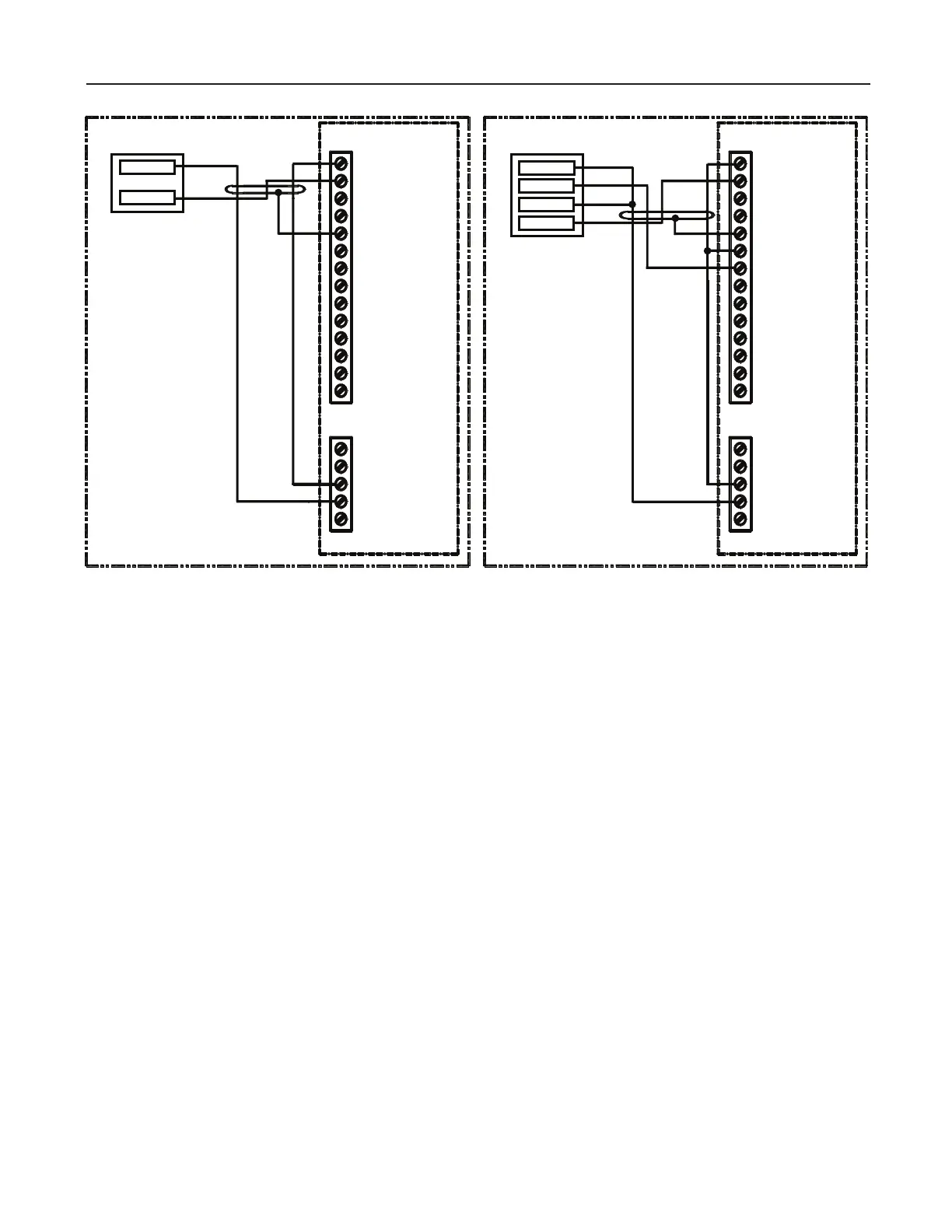
5 Shield
4
3
2 A-
1 A+
CN5
5
4 Gnd
3 +12Vdc
2
1
CN6
CN6
1
2
3 +12Vdc
4 Gnd
5
CN5
1 A+
2 A-
3
4
5 Shield
6 B+
7 B-
8
9
10
11
12
13
14
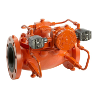
Promass
MNET Board
MNET Board
Promass, Single Pulse Promass, Dual Pulse
22
25
24
23
23/25
22/24
Promass
Figure 9. Wiring Diagram, Promass
Promass Wire Codes
Note: Pulse Inputs
• If EPLD (U24 chip) is Rev. 0, dual pulse will not function under 25 Hz. Only single pulse will count from 25 Hz
down to 3 Hz. Above 25 Hz, dual pulse will function as normal.
• If EPLD (U24 chip) is Rev. 1 or higher, dual pulse will function from 3 Hz and higher.
• Pulse doubling will not function for input pulses below 25 Hz.
• The pulse input circuitry has 1.6 kΩ of current limiting resistance “built-in” so that an external pull-up resistor is not
required when an open collector output device is connected as shown.
 Loading...