Performance Check—2465B/2467B Service
3. Check Data Hold Time
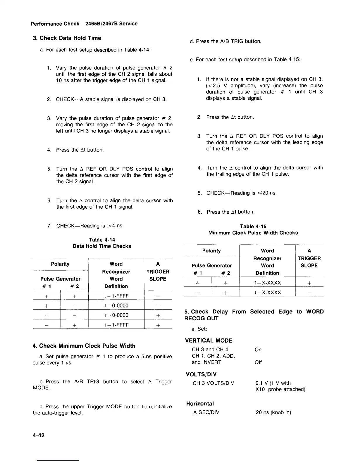
a. For each test setup described in Table 4-14:
1.
Vary the pulse duration of pulse generator # 2
until the first edge of the CH 2 signal falls about
10 ns after the trigger edge of the CH 1 signal.
2.
CHECK—A stable signal is displayed on CH 3.
d.
Press the A/B TRIG button.
e. For each test setup described in Table 4-15:
1.
If there is not a stable signal displayed on CH 3,
(<2.5 V amplitude), vary (increase) the pulse
duration of pulse generator # 1 until CH 3
displays a stable signal.
3. Vary the pulse duration of pulse generator # 2,
moving the first edge of the CH 2 signal to the
left until CH 3 no longer displays a stable signal.
4.
Press the At button.
2.
Press the At button.
3. Turn the A REF OR DLY POS control to align
the delta reference cursor with the leading edge
of the CH 1 pulse.
5. Turn the A REF OR DLY POS control to align
the delta reference cursor with the first edge of
the CH 2 signal.
6. Turn the A control to align the delta cursor with
the first edge of the CH 1 signal.
4.
Turn the A control to align the delta cursor with
the trailing edge of the CH 1 pulse.
5. CHECK—Reading is <20 ns.
6. Press the At button.
7. CHECK—Reading is >4 ns.
Table 4-14
Data Hold Time Checks
Table 4-15
Minimum Clock Pulse Width Checks
Polarity
Pulse Generator
#1 #2
+
+
—
—
+
—
—
+
Word
Recognizer
Word
Definition
1-1-FFFF
1-0-0000
T- 0-0000
T-1-FFFF
A
TRIGGER
SLOPE
—
—
+
+
4. Check Minimum Clock Pulse Width
a. Set pulse generator # 1 to produce a 5-ns positive
pulse every 1 fis.
b. Press the A/B TRIG button to select A Trigger
MODE.
c. Press the upper Trigger MODE button to reinitialize
the auto-trigger level.
Polarity
Pulse Generator
#1 #2
+
—
+
+
Word
Recognizer
Word
Definition
T-X-XXXX
l-X-XXXX
A
TRIGGER
SLOPE
+
—
5. Check Delay From Selected Edge to WORD
RECOG OUT
a. Set:
VERTICAL MODE
CH 3 and CH 4
CH 1, CH 2, ADD,
and INVERT
VOLTS/DIV
CH 3 VOLTS/DIV
Horizontal
A SEC/DIV
On
Off
0.1 V (1 V with
X10 probe attached)
20 ns (knob in)
4-42
 Loading...


