b. Connect the instrument X10 probe to the CH 4 input
connector and the probe tip to the wire on the red binding
post of the CH 1 input.
c. Set pulse generator # 1 to produce a 50-ns positive
pulse every 10 us.
d.
Set the A Trigger SOURCE to CH 4.
Performance Check—2465B/2467B Service
d.
For each test setup described in Table 4-17:
1.
Press the At button. Turn the A REF OR DLY
POS control to align the delta reference cursor
with the first edge of the CH 4 signal.
3. Turn the A control to align the delta cursor with
the rising edge of the CH 3 signal.
d.
For each test setup described in Table 4-16:
4.
CHECK—Reading is =£140 ns.
1.
Press the At button.
5. Press the At button.
2.
Turn the A REF OR DLY POS control to align
the delta reference cursor with the active edge of
the CH 4 signal.
3. Turn the A control to align the delta cursor with
the rising edge of the CH 3 signal.
4.
CHECK—Reading is =£55 ns.
5. Press the At button.
Table 4-16
Delay From Selected Edge to
WORD RECOG OUT Checks
Polarity
Pulse Generator
#1 #2
+
—
+
+
Word
Recognizer
Word
Definition
T-X-XXXX
i-X-XXXX
A
TRIGGER
SLOPE
+
—
e. Disconnect the probe on the CH 4 input.
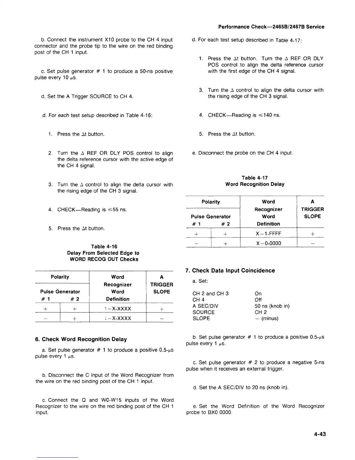
Table 4-17
Word Recognition Delay
Polarity
Pulse Generator
#1 #2
+
—
+
+
Word
Recognizer
Word
Definition
X-1-FFFF
X-0-0000
A
TRIGGER
SLOPE
+
—
7. Check Data Input Coincidence
a. Set:
CH 2 and CH 3
CH 4
A SEC/DIV
SOURCE
SLOPE
On
Off
50 ns (knob in)
CH 2
— (minus)
6. Check Word Recognition Delay
a. Set pulse generator # 1 to produce a positive
0.5-MS
pulse every 1 us.
b. Disconnect the C input of the Word Recognizer from
the wire on the red binding post of the CH 1 input.
c. Connect the Q and W0-W15 inputs of the Word
Recognizer to the wire on the red binding post of the CH 1
input.
b. Set pulse generator # 1 to produce a positive
0.5-MS
pulse every 1 fts.
c. Set pulse generator # 2 to produce a negative 5-ns
pulse when it receives an external trigger.
d.
Set the A SEC/DIV to 20 ns (knob in).
e. Set the Word Definition of the Word Recognizer
probe to BX0 0000.
4-43
 Loading...


