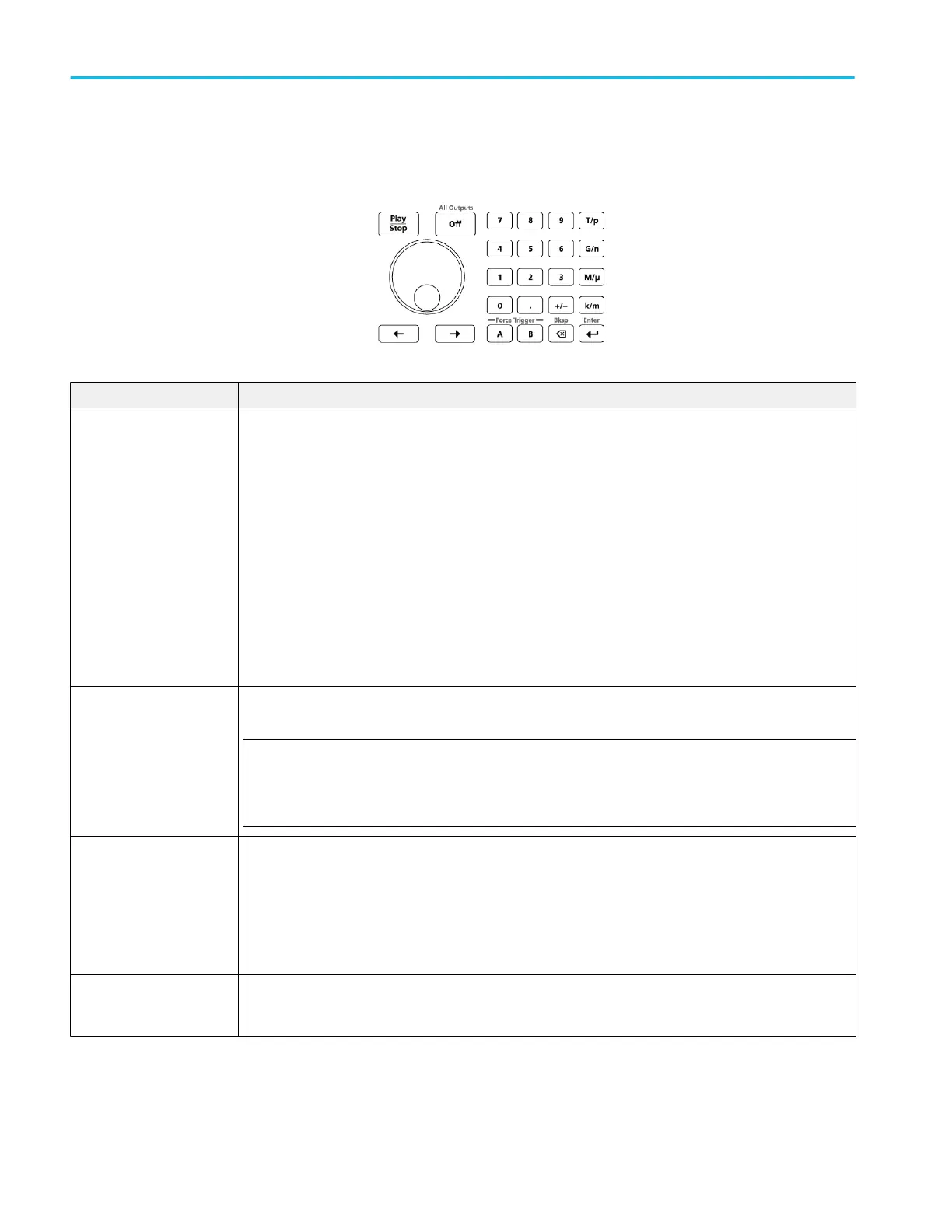
Front-panel controls
The following illustration and table describe the front panel controls.
Buttons/Keys Description
Play/Stop The Play/Stop button starts or stops playing the waveform.
The Play/Stop button displays the following lights:
■
No light - no waveform playing
■
Green - playing a waveform
■
Flashing green - preparing to play a waveform
■
Amber - play out temporarily inhibited due to a settings change
■
Red - Error preventing play out
When a waveform is playing, it is only present at the output connectors if the following conditions are met:
■
The channel is enabled.
■
The All Outputs Off is not active (outputs are connected).
General purpose knob The general purpose knob is used to increment or decrement values when a setting is enabled (selected) for
change.
NOTE. The general purpose knob operation mimics the actions of the up and down arrow keys on a
keyboard as defined by the Windows operating system. Because of this, rotating the knob when a desired
control is not selected may result in seemingly odd behavior of the control or accidental changes to some
other control.
Numeric keypad The numeric keypad is used to directly enter a numeric value into a selected control setting.
Units prefix buttons (T/p, G/n, M/μ, and k/m) are used to complete an input with the numeric keypad. You
can complete your entry by pushing one of these prefix buttons (without pressing the Enter key).
If you push the units prefix buttons for frequency, the units are interpreted as T (tera-), G (giga-), M (mega-),
or k (kilo-). If you push the buttons for time or amplitude, the units are interpreted as p (pico-), n (nano-), μ
(micro-), or m (milli-).
Left and Right Arrow buttons Use the arrow buttons to change (select) the focus of the cursor in the Frequency control box when and IQ
waveform is assigned to the channel. The Digital Up Converter (DIGUP) must be licensed to assign IQ
waveforms to a channel..
Operation basics
22 AWG5200 Series Installation and Safety Instructions

 Loading...


