DMM4040
and
4050
Safety and Installation Instructions
Electrical
Input Protection
. 1000 V all ranges
Overrange
..
...
.
....
...
. 20 % on all ranges except 1000 V dc, 1000 V ac (4050),
750 V ac (4040), Diode, and 10 A ranges
Remote Interfaces
RS-232C, DTE 9-pin, 1200 to 230400 baud (RS-232C to USB cable available to connect the Meter to a PC USB port.
See
Ac
cessories)
IEEE 488.2
LAN and "Ethernet
10/100 base T with DHCP (for
IP
_ADDRess) option"
Warranty
Three years
Electrical Specifications
Accuracy specifications are valid for
61',
digit resolution mode after
at
least a 1-hour warm-up with Auto Zero enabled.
24-hour specifications are relative
to
calibration standards and assume a controlled electromagnetic environment per
EN
61326-1:2000-11
DC
Voltage Specifications
Maximum Input ..
...
........ .
...
'"
..
...
.......... .
..
.... 1000 V on any range
Common Mode Rejection ..... .
. .. 140 dB at 50 or 60 Hz
±O
.1 %
(1
kO
unbalance)
Normal Mode Rejection .
...
.. .
. ....
60 dB for NPLC
of
1 or greater with analog filter off and power line
frequency ±0.1 %
100 dB for NPLC
of
1 or greater with analog filter
on
and power line
frequency
±0.1
%
Measurement Method .
...
....
..
..... .
.... Multi-ramp AID
AID Linearity .
..
.............
...
.. ..
..
..
.
,.
.. 0.0002 % of measurement +0.0001 % of range
Input Bias Curren!..
..
...
...
. . ....
..
.. <30 pA at 25 °C
Autozero Off Operation ... .
. ... Following instrument warm-up at calibration temperature
±1
°c
and
less than 10 minutes, add error: 0.0002 % range additional error
+5
!IV .
Analog
Fi
lter ..
...
. ........
..
...
... ...
..
..
...
..... .
..
....... ... . When using the analog filter, specifications are relative to within one
hour of using the ZERO function for that range and NPLC
se
tting .
DC
Ratio
.. .. ..
.
......
Accuracy is
+1-
(Input accuracy + Reference accuracy), where Input
accuracy
=
DC
Voltage accuracy for the
HI
to
LO
Input
(in
ppm of the
Input voltage), and Reference accuracy
= DC Voltage accuracy for the
HI
to LO (Sense) Reference (in ppm of the Reference voltage).
•
Settling Considerations .....
......
.....
...
..
..
...
.... .
..
...
. Measurement settling times are affected
by
source impedance, cable
dielectric characteristics, and input Signal changes.
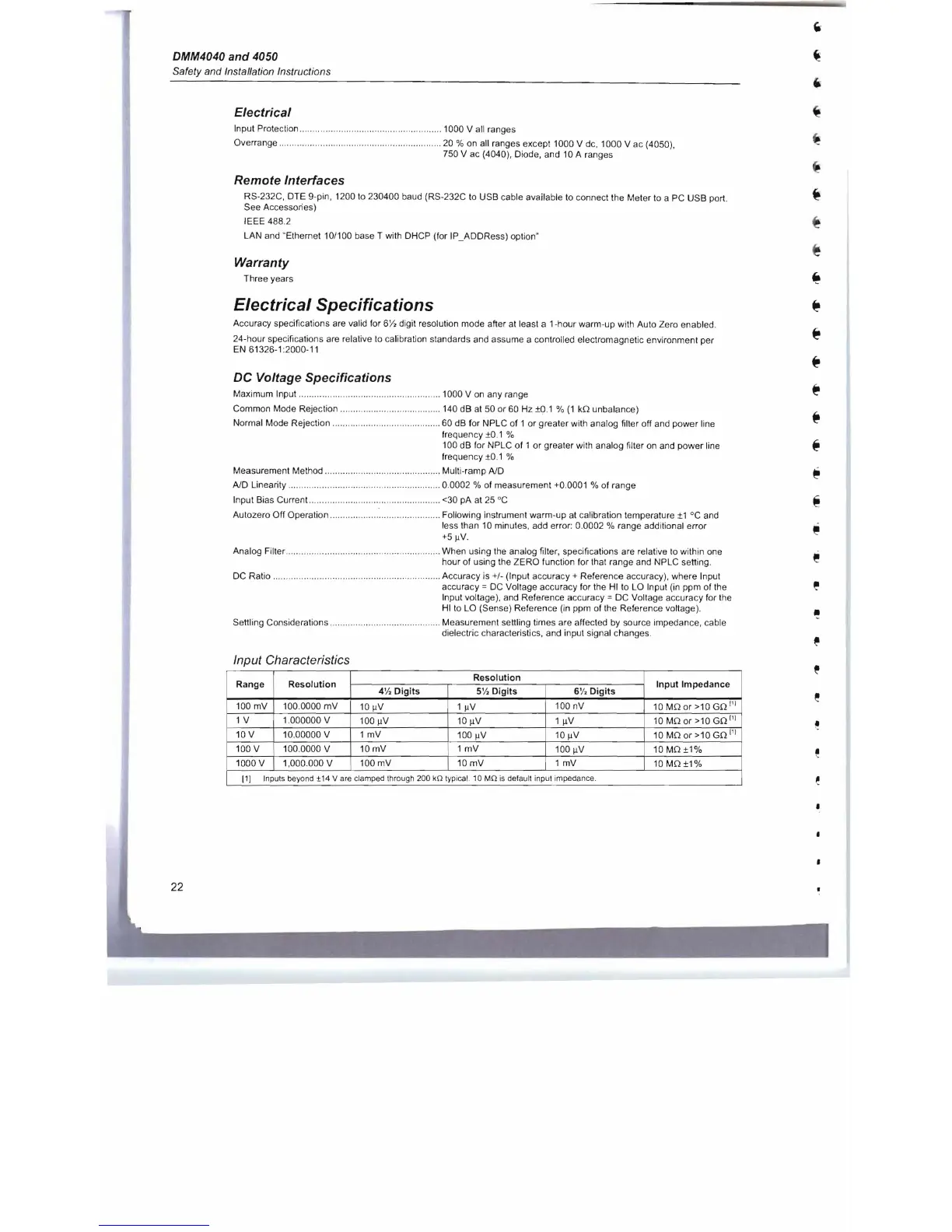
Input Characteristics
Range
Resolution
Resolution
Input
Impedance
4
'1,
Digits
5'
/,
Digits
6'
/'
Digits
100 mV 100.0000
mV
10
!IV 1 !IV
100 nV 10 MO or >10 GO
1'
1
1 V 1.000000 V
100 !IV
1
0
llV
1
IlV
10
MO
or >10 GO
1'1
10 V 10.00000 V 1 mV
100 !IV
10llV
10
MO
or >10 GO
I
'
I
100 V 100.0000 V
10mV
1
mV
100llV
10
MO
±1%
1000 V 1,000.000 V
100 mV 10 mV 1 mV
10
MO±1%
[1
[
Input
s
beyond
+14
V
are
clamped
through
200
kO
typ
i
cal.
10 MO
is
default
input
impedance
.
22

 Loading...


