EasyManuals Logo
Home>Tektronix>Test Equipment>DPO4104

Tektronix DPO4104 User Manual

Tektronix DPO4104
359 pages
To Next Page IconTo Next Page
To Previous Page IconTo Previous Page
Page #103 background imageLoading...
Page #103 background image
Get Acquainted with the Instrument
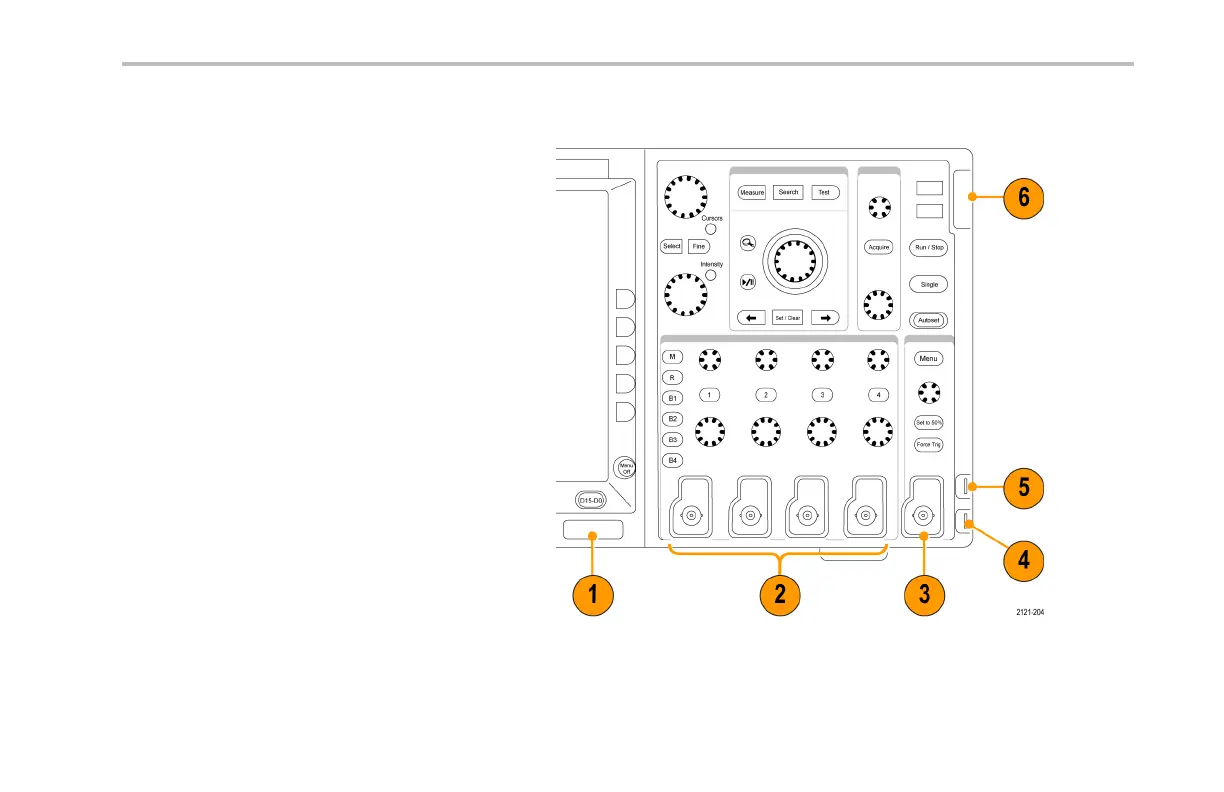
Front-Panel Connectors
1. Logic Probe Connector (on
MSO4000 models only)
2. Channel 1, 2,(3, 4 ). Channel inputs with
TekVPI Versatile Probe Interface.
3. Aux In. Trigger level range is adjustable
from +8 V to –8 V. The maximum input
voltage is 400V peak, 25 0V RMS. Input
resistance is 1 M ± 1% in parallel with
13 pF ±2 pF.
4. PROBE COMP. Square wave signal
source to compensate probes. Output
voltage: 0 2.5V, amplitude ± 1% behind
1k ±2%. Frequency: 1 kHz.
5. Ground.
6. Application Module Slots.
MSO4000 and DPO4000 Series Oscilloscopes User Manual 77

Table of Contents

Other manuals for Tektronix DPO4104

Questions and Answers:

Question and Answer IconNeed help?

Do you have a question about the Tektronix DPO4104 and is the answer not in the manual?

Tektronix DPO4104 Specifications

General IconGeneral
BrandTektronix
ModelDPO4104
CategoryTest Equipment
LanguageEnglish

Related product manuals