Home
Tektronix
Test Equipment
DPO5000 Series
Tektronix DPO5000 Series Service Manual
4
of 1
of 1 rating
167 pages
Give review
Manual
Specs
To Next Page
To Next Page
To Previous Page
To Previous Page
Loading...
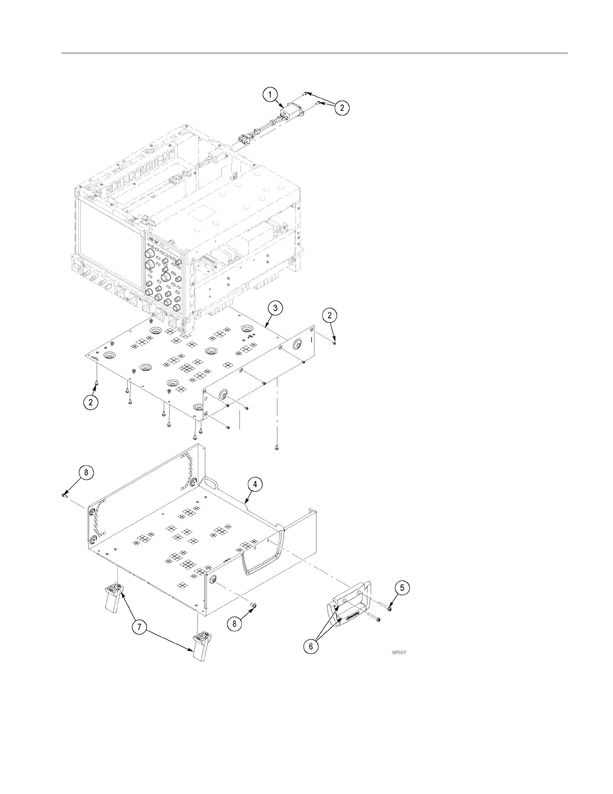
Replaceable
Parts
(MSO70000/C,
DSA/DPO70000C
Series)
Figure
5-18:
External
parts
2
(MSO70000/C,
DSA/DPO70000C
Series)
MSO70000/C,
DSA70000B/C,
DPO70000B/C,
D
PO7000,
MSO5000,
DPO5000
Series
5–35
138
140
Table of Contents
Table of Contents
7
General Safety Summary
13
Service Safety Summary
15
Preface
17
Manual Structure
17
Manual Conventions
17
Getting Started
19
Where to Find Operating Information
21
Theory of Operation
23
Module Overviews (DPO7000 Series, DSA/DPO70000B/C Series)
25
Figure 2-1: Block Diagram (DPO7000 Series)
28
Figure 2-2: Block Diagram (DSA7/DSA70000B/C Series)
29
Module Overviews (MSO70000/C Series)
30
Figure 2-3: Block Diagram (MSO70000/C Series)
33
Module Overviews (MSO/DPO5000 Series)
34
Figure 2-4: Block Diagram (MSO/DPO5000 Series)
37
Adjustment Procedures
39
Adjustment Interval
41
Adjustment after Repair
41
Adjustment
41
Maintenance
43
Preventing ESD
45
Inspection and Cleaning
46
General Care
46
Interior Cleaning
46
Exterior Cleaning
46
Flat Panel Display Cleaning
47
Table 4-1: External Inspection Checklist
47
Table 4-2: Internal Inspection Checklist
48
Returning the Instrument for Service
50
Removal and Installation Overview
51
Preparation
51
Table 4-3: Required Equipment for Module Removal
51
Module Removal (DPO7000 Series)
52
Figure 4-1: DPO7000 Series Module Locations
52
Table 4-4: DPO7000 Series Module Removal
53
Module Removal (DSA/DPO70000B Series)
54
Figure 4-2: Module Locations
54
Table 4-5: Module Removal (DSA/DPO70000B Series)
55
Μatx and Power Interface Removal (DPO7000 Series)
56
Figure 4-3: Removing the Μatx/Power Interface Assembly
57
Module Removal (MSO/DPO5000 Series)
58
Figure 4-4: Module Locations (MSO/DPO5000 Series)
59
Troubleshooting (DPO7000 Series, MSO70000/C Series, DSA/DPO70000B/C Series)
60
Service Level
60
Check for Common Problems
60
Table 4-6: Failure Symptoms and Possible Causes
60
Equipment Required
62
Fault Isolation Procedure
62
Figure 4-5: Primary Troubleshooting Tree
63
Figure 4-6: Location of Power-On and Over-Current Leds
64
Table 4-7: Power-On and Over-Current Leds
64
Table 4-8: Power Supply Voltages
65
Figure 4-7: Power Supply Test Points
66
Instrument Diagnostics
67
Figure 4-8: Diagnostics Control Panel
68
Table 4-9: Diagnostic Tests
69
Software Updates
70
After Repair
71
Μatx BIOS Error Messages
71
Table 4-10: Μatx BIOS Error Messages
71
Table 4-11: 039-0173-XX and 065-0745-XX Μatx POST Codes
72
Table 4-12: 039-0185-XX Μatx POST Codes
75
BIOS Beep Codes
85
Table 4-13: 039-0173-XX and 065-0745-XX Μatx Beep Codes
85
Table 4-14: 039-0185-XX Μatx Beep Codes
86
Table 4-15: 039-0188-XX Μatx Beep Codes
86
Installing an Authorization Key
87
Hard Disk Drive Repair
87
Troubleshooting (MSO/DPO5000 Series)
89
Software Updates
89
After Repair
89
Service Level
90
Fault Isolation Procedure
90
Table 4-16: Failure Symptoms and Possible Causes
90
Figure 4-9: Troubleshooting Tree (MSO/DPO5000 Series)
91
Table 4-17: LED Definitions
94
Table 4-18: DS10 Errors by Speed and Duration
95
Table 4-19: DS10 Errors by Number of Flashes, with Related Voltages
95
BIOS Error Messages
96
Table 4-20: BIOS POST Codes: ECM-945GM Series
96
BIOS Beep Codes
102
Hard Disk Drive Repair
102
Table 4-21: BIOS Beep Codes
102
Replaceable Parts
103
Replaceable Parts Overview
105
Parts Ordering Information
105
Using the Replaceable Parts List
106
Replaceable Parts (DPO7000 Series)
107
Table 5-1: Replaceable Parts - External (DPO7000 Series)
107
Figure 5-1: External Parts (DPO7000 Series)
108
Table 5-2: Replaceable Parts - Front Panel and Display (DPO7000 Series)
109
Figure 5-2: Front Panel and Display (DPO7000 Series)
110
Table 5-3: Replaceable Parts - Power Supply and Fans (DPO7000 Series)
111
Figure 5-3: Power Supply and Fans (DPO7000 Series)
112
Table 5-4: Replaceable Parts - Μatx Motherboard (DPO7000 Series)
113
Figure 5-4: 039-0173-XX and 065-0745-XX Μatx Motherboard (DPO7000 Series)
114
Figure 5-5: 039-0185-XX Μatx Motherboard (DPO7000 Series)
115
Table 5-5: Replaceable Parts - Power Interface and Acquisition Assemblies (DPO7000 Series)
116
Figure 5-6: Power Interface and Acquisition Assemblies (DPO7000 Series)
117
Table 5-6: Replaceable Parts - Drives (DPO7000 Series)
118
Figure 5-7: Drives (DPO7000 Series)
119
Replaceable Parts (DSA/DPO70000B Series)
120
Table 5-7: Replaceable Parts - External 1 (DSA/DPO70000B Series)
120
Figure 5-8: External Parts 1 (DSA/DPO70000B Series)
121
Table 5-8: Replaceable Parts - External 2 (DSA/DPO70000B Series)
122
Figure 5-9: External Parts 2 (DSA/DPO70000B Series)
123
Table 5-9: Replaceable Parts - Front Panel and Display (DSA/DPO70000B Series)
124
Figure 5-10: Front Panel and Display (DSA/DPO70000B Series)
125
Table 5-10: Replaceable Parts - Power Supply and Fans (DSA/DPO70000B Series)
126
Figure 5-11: Power Supply and Fans (DSA/DPO70000B Series)
127
Table 5-11: Replaceable Parts - Μatx Assembly (DSA/DPO70000B Series)
128
Figure 5-12: 039-0173-XX and 065-0745-XX Μatx (DSA/DPO70000B Series)
129
Figure 5-13: 039-0185-XX Μatx Assembly (DSA/DPO70000B Series)
130
Figure 5-14: Acquisition Assembly (DSA/DPO70000B Series)
131
Table 5-12: Replaceable Parts - Acquisition Assembly (DSA/DPO70000B Series)
131
Table 5-13: Replaceable Parts - Interface Board (DSA/DPO70000B Series)
132
Figure 5-15: Interface Board (DSA/DPO70000B Series)
133
Table 5-14: Replaceable Parts - Drives (DSA/DPO70000B Series)
134
Figure 5-16: Drives (DSA/DPO70000B Series)
135
Replaceable Parts (MSO70000/C, DSA/DPO70000C Series)
136
Table 5-15: Replaceable Parts - External 1 (MSO70000/C, DSA/DPO70000C Series)
136
Figure 5-17: External 1 (MSO70000/C, DSA/DPO70000C Series)
137
Table 5-16: Replaceable Parts - External 2 (MSO70000/C, DSA/DPO70000C Series)
138
Figure 5-18: External Parts 2 (MSO70000/C, DSA/DPO70000C Series)
139
Table 5-17: Replaceable Parts - Front Panel (MSO70000/C, DSA/DPO70000C Series)
140
Figure 5-19: Front Panel and Display (MSO70000/C, DSA/DPO70000C Series)
141
Figure 5-20: Drive Bay 1 (MSO70000/C, DSA/DPO70000C Series)
143
Figure 5-21: Drive Bay 2 (MSO70000/C, DSA/DPO70000C Series)
145
Figure 5-22: Interface Board (MSO70000/C, DSA/DPO70000C Series)
147
Figure 5-23: Power Supply (MSO70000/C, Dsa/Dpo70000Cseries)
149
Figure 5-24: Acquisition Assembly (MSO70000/C, DSA/DPO70000C Series)
151
Figure 5-25: MSO Module (MSO70000/C Series)
153
Figure 5-26: Μatx 1 (MSO70000/C, DSA/DPO70000C Series)
155
Replaceable Parts (MSO/DPO5000 Series)
158
Other manuals for Tektronix DPO5000 Series
Manual
1002 pages
User Manual
218 pages
Technical Reference
352 pages
4
Based on 1 rating
Ask a question
Give review
Questions and Answers:
Need help?
Do you have a question about the Tektronix DPO5000 Series and is the answer not in the manual?
Ask a question
Tektronix DPO5000 Series Specifications
General
Brand
Tektronix
Model
DPO5000 Series
Category
Test Equipment
Language
English
Related product manuals
Tektronix DPO5054
213 pages
Tektronix DPO5034
213 pages
Tektronix DPO5054B
222 pages
Tektronix DPO5034B
222 pages
Tektronix DPO5104
213 pages
Tektronix DPO5204
213 pages
Tektronix DPO5204B
222 pages
Tektronix DPO5104B
222 pages
Tektronix DPO2012
272 pages
Tektronix DPO7104
213 pages
Tektronix DPO7254C
222 pages
Tektronix DPO7104C
222 pages