Troubleshooting (DPO7000 Series, MSO70000/C Series, DSA/DPO70000B/C Series)
Isolating to a B
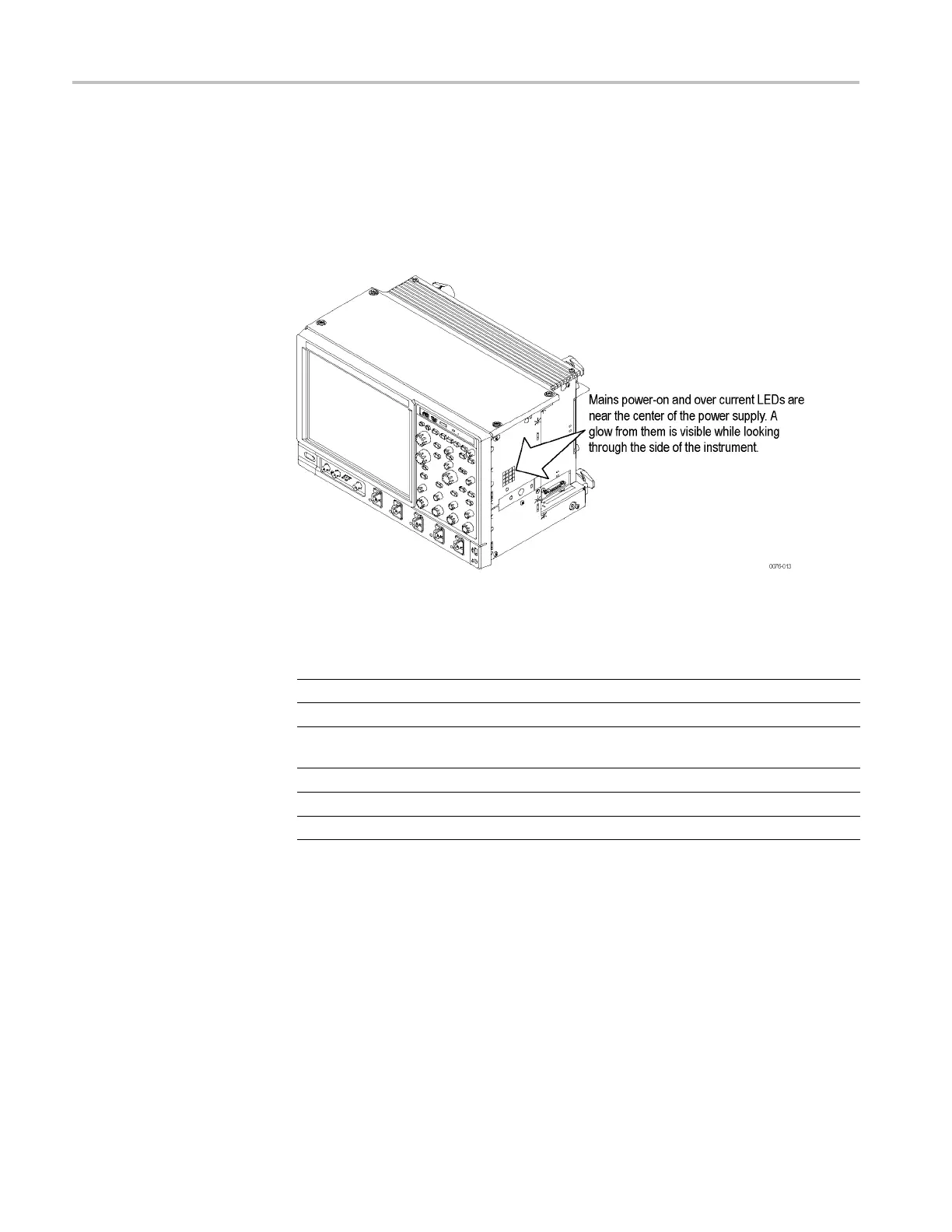
oard if Power Will Not Come Up, DPO7000 Series. If the instrument
is in standby mode (plugged in, but not turned on), a red light is visible through
the right side of the instrument. The location o f the red light is shown in the
following illustration. (See Figure 4-6.)
If the instrument is On, the red light should be off. A red light when the instrument
in On means that there is a problem with one of the power supplies.
Figure 4-6: Location of power-on and over-current LEDs
Table 4-7: Power-on and over-current LEDs
LED Supply Description
DS200
+15 VA
Green when supply is operating within tolerance.
DS201
+5 VA
Green when supply is operating within tolerance.
DS202 N/A Red if any of the supplies (+15 VA, +5 VA, +1.8 VD,
-15 VA, and -5 VA ) are out of tolerance.
DS203
-5 VA
Green when supply is operating within tolerance.
DS204
-15 VA
Green when supply is operating within tolerance.
DS330
+1.8 VD
Green when supply is operating within tolerance.
Remove boards one at a time to locate a fault (the Display board, Acquisition
board, Power interface board, and the μATX board). If this does not identify the
problem, check the IEC power cable.
If this process did not correct the problem, replace the power supply.
Isolating to a Board if Power Will Not Come Up, DPO70000B and DSA70000B
Series. Remove boards one at a time to locate a fault (the Display board,
Acquisition board, Power distribution board, PCI backbone board, and the μATX
board). If this does not identify the problem, check the IEC power cable.
If this process did not correct the problem, replace the power supply.
4–20 MSO70000/C, DSA70000B/C, DPO70000B/C, DPO7000, MSO5000, DPO5000 Series
 Loading...


