Analyzing wavef
orms
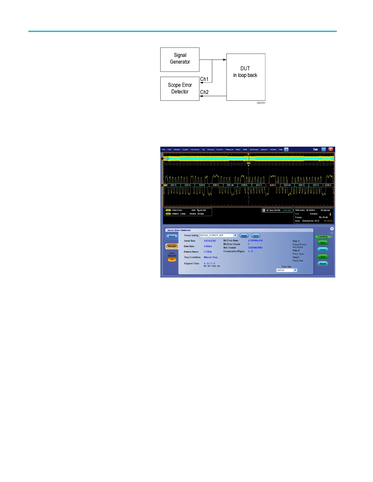
20. To avoid having
to rearrange the cables
after the Learn operation, you m ay split
the output of the signal generator, putting
one branch int
o the Error Detector and
one branch into the DUT. H ere the
Learn Operation is done on Ch1, but
the actual er
ror detection occurs on
Ch2. You can adjust the amplitude of
the signal generator to account for the
loss due to sp
litting the signal. This
works because the Error D etector learn
operation stores the signal test pattern
into non-ch
annel-specific memory.
21. When the Er
ror Detector is driven from
the user interface, bus triggers are used
whenever possible, so that bus decoding
is automat
ically enabled. The Decoding
indicates the location of the error in
the signal by highlighting the decoded
valueinr
ed, as shown in the screen
shot below. You can use additional
oscilloscope channels to simultaneously
probe ot
her signals to debug the cause
of the error.
140 MSO/DPO70000DX, MSO/DPO70000C, DPO7000C, and MSO/DPO 5000B Series U ser M anual
 Loading...

