Specifications
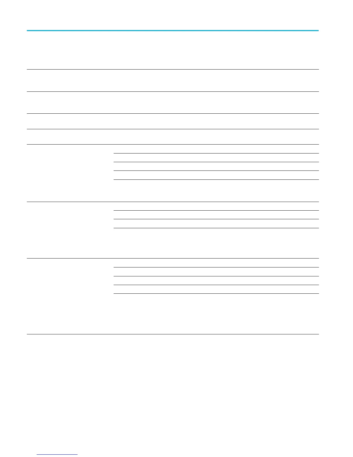
Table 4: Trigger specifications (cont.)
Characteristic Description
Lowest frequency for successful
operation of "Set Level to 50%"
function, typical
45 Hz
Logic-type or logic qualifi ed trigger
or events-delay sensitivities, DC
coupled, typical
1.0 division from DC to maximum bandwidth
Pulse-type runt trigger sensitivities,
typical
1.0 division from DC to maximum bandwidth
Pulse-type trigger width and glitch
sensitivities, typical
1.0 division
For all vertical settings, the minimums are:
Trigger type Pulse width Re-arm time Time between channels
Logic Not applicable 2 ns 1 ns
Time Qualified Logic
4ns 2ns 1ns
Logic-type triggering, minimum logic
or rearm time, typical
For logic, time between channels refers to the length of time a logic state derived from more
than one channel must exist to b e recognized. For events, the time is the minimum time
between a main and delayed event that will be recognized if more than one channel is used.
For all vertical settings, the minimums are:
Clock active Clock inactive
User hold time + 2.5 ns 2 ns
Minimum c lock pulse widths for
setup/hold time violation trigger,
typical
An active pulse width is the width of the clock pulse from its active edge (as defined in the
Clock Edge lower-bezel menu item) to its inactive edge. A n inactive pulse width is the width
of the pulse from its inactive edge to its active edge.
The User hold time is the number selected by the user.
Feature Min Max
Setup time
–0.5 ns 1.0 ms
Hold time 1 ns 1.0 ms
Setup + Hold time
0.5 ns 2.0 ms
Setup/hold violation trigger, setup
and hold time ranges
Input coupling on clock and data channels must be the same.
For Setup time, positive numbers mean a data transition before the clock.
For Hold time, positive numbers mean a data transition after the clock edge.
Setup + Hold time is the algebraic sum of the Setup Time and Hold Time that you
programmed.
14 MSO4000B and DPO4000B Series Specifications and Performance Verification

 Loading...


