Performance Verification
Check DC Gain Accuracy
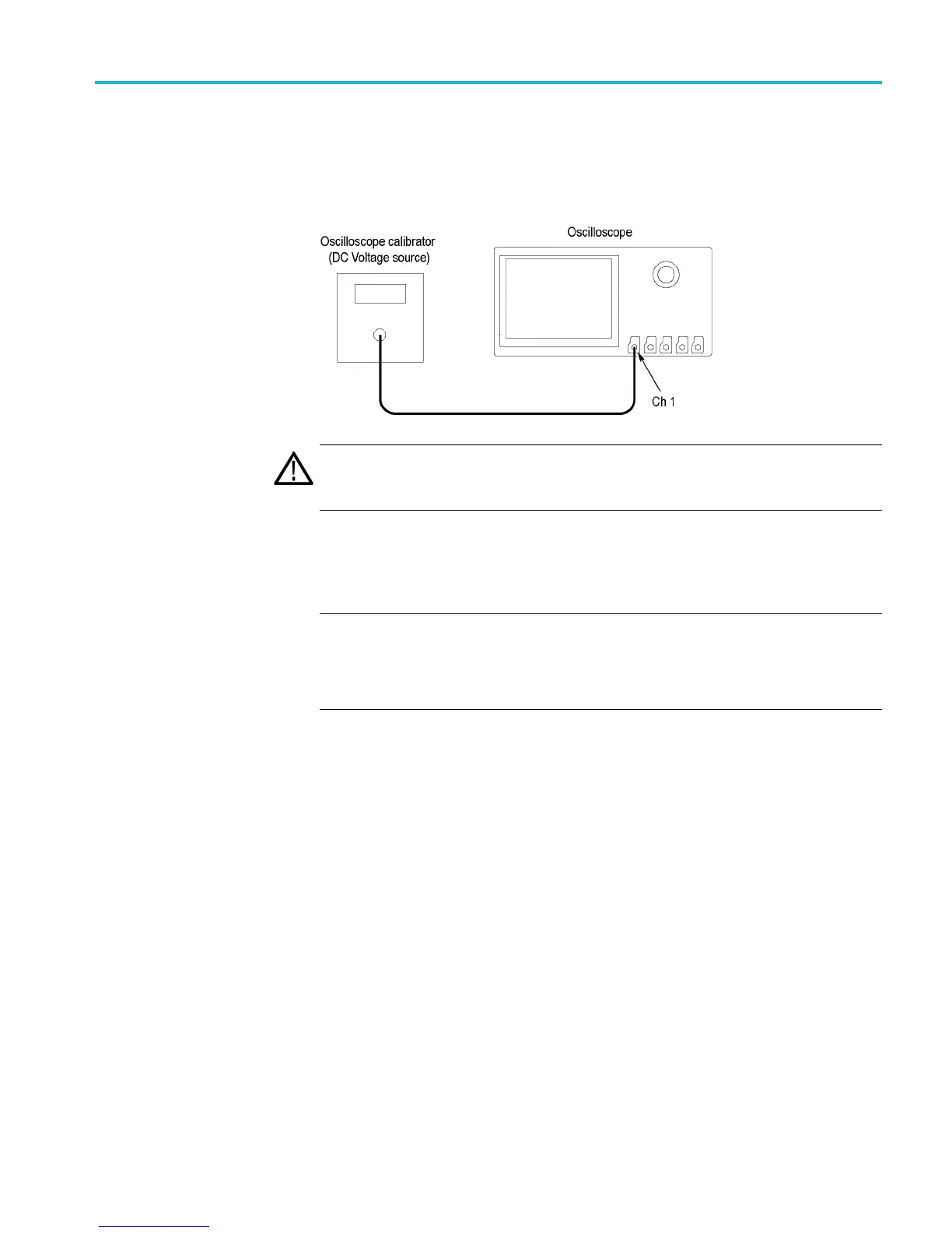
This test check
s the DC gain accuracy.
1. Connect the oscilloscope to a DC voltage source. If using the Fluke 9500
calibrator, c
onnect the calibrator head to the oscilloscope channel to test.
WARNING.
The generator is capable of providing dangerous voltages. Be sure to
set the generator to off or 0 volts before connecting, disconnecting, and/or moving
the test hookup during the performance of this pro cedure.
2. Push the front-panel Default Setup button. The Termination (input
impedance) is set to 1 MΩ and channel 1 input is selected.
NOTE. 50 Ω termination testing (steps 4 through 11) is required only for
MSO4104B, DPO4104B, MSO4104B-L, DPO4104B-L, MSO4102B-L,
DPO4102B-L, MSO4102B, and DPO4102B models.
1MΩ termination t esting (step 14 ) is required for all models.
3. For MSO4104B, DPO4104B, MSO4104B-L, DPO4104B-L, MSO4102B-L,
DPO4102B-L, MSO4102B, and DPO4102B models, perform steps 4
through 14. For other models, go to step 14 now.
4. Select 50 Ω input impedance as follows:
a. Set the calibrator to 50 Ω output impedance.
b. Push the channel 1 button.
c. Set the Termination (input impedance) to 50 Ω.
5. Set the bandwidth to 20 MHz as follows:
a. Push the lower-bezel Bandwidth button.
b. Push the 20 MHz side-bezel button to select the bandwidth.
MSO4000B and DPO4000B Series Specifications and Performance Verification 59

 Loading...


