Performance Verification
Check Input Impedance
(Resistance)
This test check
s the Input Impedance.
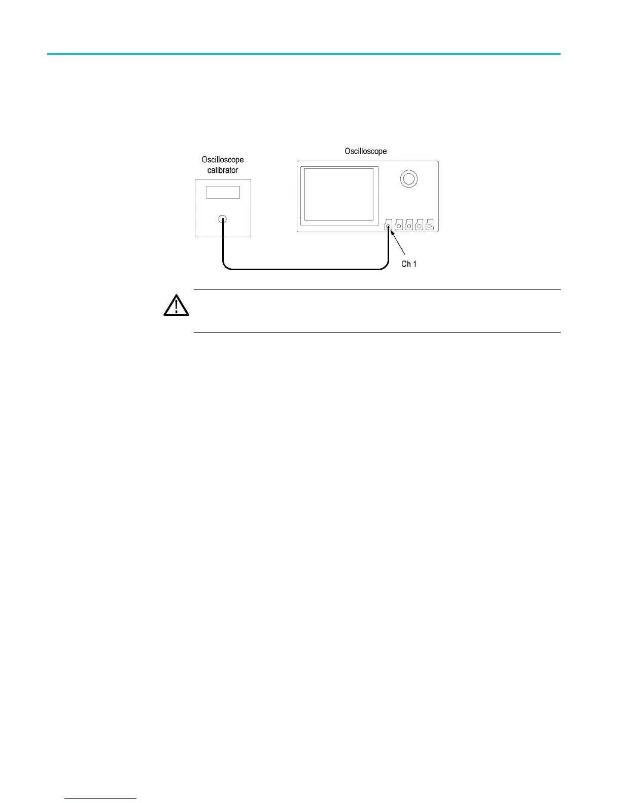
1. Connect the output of the oscilloscope calibrator (for example, Fluke 9500) to
the oscillosc
ope channel 1 input, as shown below.
WARNING.
The generator is capable of providing dangerous voltages. Be sure to
set the generator to o ff or 0 volts before connecting, disconnecting, and/or moving
the test hookup during the performance of this pro cedure.
2. Push the front-panel Default Setup button.
3. Set the
impedance to 1 MΩ as follows:
a. Push the channel 1 button.
b. Set the Termination (input impedance) to 1MΩ.
4. Set the Vertical Scale to 10 mV/division.
5. Measure the input resistance of the oscilloscope with the calibrator. Record
this value in the test record.
6. Repeat steps 4 and 5 for each vertical scale setting in the test record.
7. Repeat the tests at 50 Ω as follows:
a. Se
t the calibrator impedance to 50 Ω.
b. Set the Termination (input impedance) to 50 Ω.
c. Repeat steps 4 through d.
8. Repeat the procedure for all remaining channels as follows:
a. Push the front-panel channel button to deselect the channel that you
already tested.
b. Connect the calibrator to the input for the next channel to be tested.
c. Starting from step 3, repeat the procedure for each channel.
56 MSO4000B and DPO4000B Series Specifications and Performance Verification

 Loading...


