Pinpoint Trigge
rs
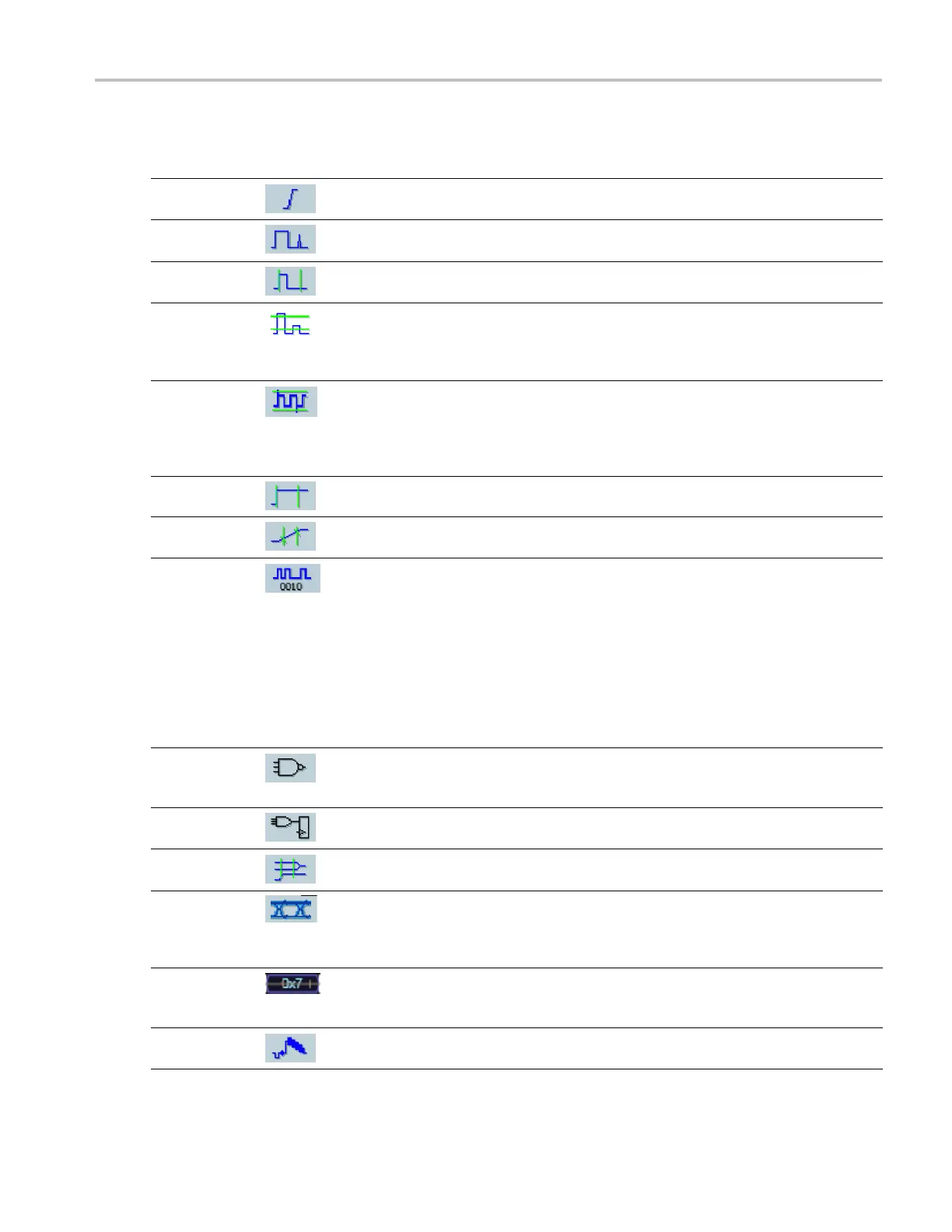
Trigger Selections
Trigger Type Trigger Conditions
Edge
Trigger on a rising or falling edge, as defined by the slope control. Coupling choices
are DC, AC, LF R eject, HF Reject, and Noise R eject.
Glitch
Trigger on a pulse narrower (or wider) than the specified width or ignore glitches
narrower (or wider) than the specified width.
Width
Trigger on pulses that are inside or outside a specified time range. Can trigger
on positive or negative pulses.
Runt
Trigger on a pulse amplitude that crosses one threshold but fails to cross a second
threshold before recrossing the first. Can detect positive or negative runts, or only
those wider than a specified width. These pulses can also be qualified by the logical
state of other channels.
Window
Trigger when the input signal rises above an upper threshold level or falls b elow a
lower threshold level. Trigger the instrument as the signal is entering or leaving the
threshold window. Qualify the trigger event in terms of time by using the Trigger
When Wider option, or by the logical state of other channels using the Trigger When
Logic option.
Timeout
Trigger when no pulse is detected within a specified time.
Transition
Trigger on pulse edges that traverse between two thresholds at faster or slower rates
than the specified time. The pulse edges can be positive or negative.
Serial Trigger on 64-bit serial pattern at data rates up to 1.25 Gb/s (<4 GHz models) and
1 to 4 8b10b symbols at data rates up to 3.125 Gb/s (≥4 GHz models only) or
6.25 Gb/s (≥4 G Hz B models). Lock on a pseudo-random bit sequence. Requires
Option PTM or PTH. This mode includes clock recovery. Push the Push to Set
50% knob to reinitialize clock recovery.
Pattern Lock automatically finds and locks on a l ong repeating pseudo-random
bit sequence (PRBS). This lock means that the instrument knows the bit length of
the pseudo-random bit sequence and can predict when the cycle repeats. Pattern
Lock enables the instrument to take samples at specific locations in a data pattern
with outstanding time base accuracy.
Pattern
Trigger when logic inputs cause the selected function to become True or False. You
can also s pecify that the logic conditions must be satisfied for a specificamountof
time before triggering.
State Trigger when all of the logic inputs to the selected logic function cause the function to
be True or False w hen the clock input changes state.
Setup/ Hold
Trigger when a logic input changes state inside the setup and hold times relative to
the clock. The mode triggers on a setup and hold violation.
Comm Trigger with mask testing on communications codes and standards (analog channels
only). The controls work together to define the parameters for the trigger event
(availablewithOptionMTMorMTHonsomeinstruments). This mode includes clock
recovery. Push the Push to Set 50% knob to reinitialize clock recovery.
Bus
Trigger on components (such as a specified address) of a bus that you define.
With some instruments and options, trigger types include parallel, SPI, RS-232,
USB, and I
2
C triggers.
Video
Trigger on specified fields or lines of a composite video signal (DPO7000, MSO5000,
and DPO5000 Series only). Only composite signal formats are supported.
MSO70000/C, DPO/DSA70000B/C, DPO7000, and MSO/DP O5000 Series U ser M anual 71
 Loading...

