Maintenance
P6015A Instruction Manual
2–13
Mechanical Disassembly and Assembly
This section contains mechanical procedures to aid in the replace-
ment of parts within the probe head and compensation box
assemblies.
NOTE. Perform the long-form compensation procedure after
replacing a part.
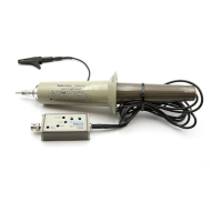
Probe Head
The probe head consists of the parts shown in Figure 2–4. Refer to
that figure while performing the following steps to replace the inner
body or other parts.
Do Not Remove Rubber Ring
CAUTION. Do not attempt to remove the rubber cushioning ring at
the front of the inner probe body or the probe may be damaged and
its high voltage performance degraded. This ring is firmly attached
with an adhesive and is not designed to be removed.
Do Not Disassemble Inner Body
CAUTION. Do not attempt to disassemble the inner body assembly.
There are no user serviceable components in the inner body
assembly, and attempting to open the inner body assembly may result
in damage to its internal structure.