Table of Contents
P6015A Instruction Manual
iii
List of Figures
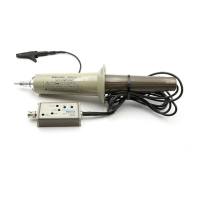
Figure 1–1: The P6015A High-Voltage Probe 1–2. . . . . . . . . . . .
Figure 1–2: Compensation Box with Readout Option 1–3. . . . .
Figure 1–3: Assembling the P6015A 1–5. . . . . . . . . . . . . . . . . . .
Figure 1–4: Maximum Input Voltage Derating
(DC + Peak AC) 1–12. . . . . . . . . . . . . . . . . . . . . . . . . . . . . . . . .
Figure 1–5: Peak Pulse Derating 1–13. . . . . . . . . . . . . . . . . . . . . .
Figure 1–6: Zones Affected by Compensation Adjustments 1–18
Figure 1–7: Humidity Derating Chart 1–26. . . . . . . . . . . . . . . . . .
Figure 1–8: Typical Input Impedance and Phase 1–26. . . . . . . . .
Figure 2–1: Access to Long-Form Adjustments 2–5. . . . . . . . . .
Figure 2–2: Adjustment Locations 2–7. . . . . . . . . . . . . . . . . . . . .
Figure 2–3: Periods Affected by Compensation
Adjustments 2–8. . . . . . . . . . . . . . . . . . . . . . . . . . . . . . . . . . . .
Figure 2–4: Removal and Replacement of Probe Head 2–14. . . .
Figure 2–5: P6015A Exploded View 2–20. . . . . . . . . . . . . . . . . . . .
 Loading...