Reference
12
PS280 & PS283 User Manual
In stacked mode, you connect the negative output terminal of one
variable power supply to the positive output terminal of the other.
The stacked configuration allows you to test a circuit requiring
between 30 and 60 V. A stacked configuration can be either floating
or ground-referenced.
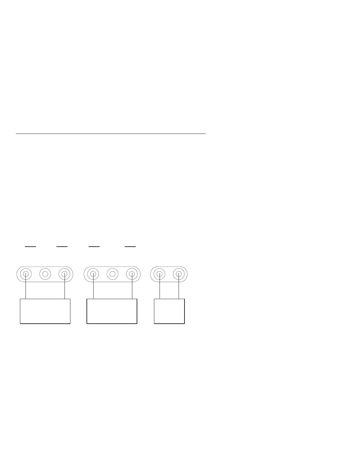
Floating. In the independently floating mode, each variable power
supply provides from 0 to 30 V at 0 to 2 A (0 to 1 A for the PS283).
Figure 4 shows each of the three power supplies connected to a
separate load.
SLAVE MASTER
5V FIXED 3A
Load 3
0 to 30 V
0 to 2 A (PS280)
0 to 1 A (PS283)
Load 2 Load 1
0 to 3 A
GND
0 to 2 A (PS280)
0 to 1 A (PS283)
0 to 30 V
5V
GND
Figure 4: Independent Floating Application
The tracking switches are disengaged for independent operation. The
left voltage and current control knobs control the outputs for the
slave variable power supply, and the right knobs do the same for the
master power supply. All outputs are electrically independent.
To test a circuit in the independently floating mode, follow these
steps:
1. Press the POWER button to apply power to the PS280 or PS283.
2. Rotate the VOLTAGE knob to zero.
3. Determine the polarity of your device.

 Loading...


