TAS 200 Series Performance Verification
Handheld and Benchtop Instruments Basic Service
9
Vertical Check
The following checks verify the vertical accuracy of your oscilloscope.
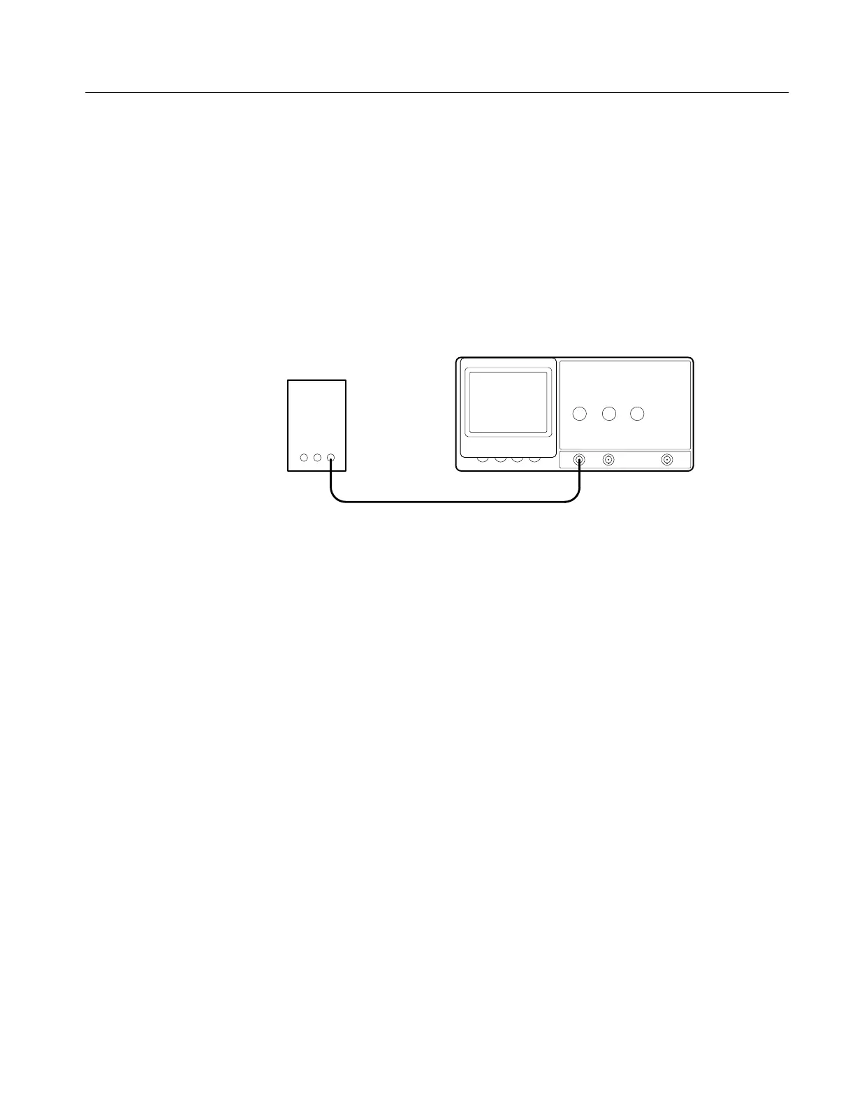
To check DC gain accuracy, perform the following steps.
1. Use the 50 W precision coaxial cable to connect the standard amplitude
output of the DC calibration generator to the TAS 200 series oscilloscope
CH 1 (CH 2) input. See Figure 2 below.
Calibration
generator
Precision cable
Figure 2: Gain and Voltage Check Setup
2. Set up the oscilloscope as follows:
VERTICAL MODE CH1 (CH2)
CH 1 (CH 2) AC-DC DC
CH 1 (CH 2) VOLTS/DIV 1 mV
TRIGGER MODE AUTO
HORIZONTAL SEC/DIV 0.5 ms
CH 1 (CH 2) GND Out (release)
3. Set the oscilloscope CH 1 VOLTS/DIV Scale and calibration generator
output to each of the values listed in Table 13; then verify that the readings
on the oscilloscope remain within the limits of the Displayed Signal
Accuracy.
DC Gain Accuracy
 Loading...

