TAS 200 Series Performance Verification
Bench Test Instruments and Handheld Oscilloscopes Basic Service
17
Table 16: X10 MAG time base accuracy
HORIZONTAL
SEC/DIV
Time marker
setting
Time mark to graticule over
center 8 divi sions
10 ns 10 ns ±0.64 division
20 ns 20 ns ±0.64 division
50 ns 50 ns ±0.64 division
12. Set the oscilloscope HORIZONTAL X10 MAG push switch to the off
position (out).
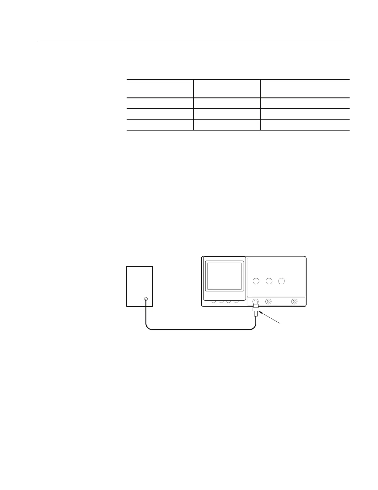
Trigger Check
The following check verifies the trigger accuracy of your oscilloscope.
1. Use the 50 Ω precision coaxial cable to connect the output of the leveled
sine wave generator to the 50 Ω termination; then connect the 50 Ω
termination to the TAS 200 series instrument CH 1 input. See Figure 5
below.
Sine Wave
Generator
Precision Cable
50 Ω Termination
Figure 5: Trigger level check setup
2. Set up the oscilloscope as follows:
VERTICAL MODE CH1
CH 1 VOLTS/DIV 1 V
CH 1 AC-DC DC
CH 1 GND Out (release)
HORIZONTAL SEC/DIV .5 s
TRIGGER M ODE AUTO
TRIGGER LEVEL Midway
 Loading...

