Performance Verification
15. Push Set To 50%.
Adjust Trigger Level as necessary and then check that
triggering is stable.
16. Disconnect the test setup.
17. Repeat steps 1 through 16 for all input channels.
Check External Edge
Trigger Sensitivity
This test checks the edge trigger sensitivity for the external trigger.
1. Set up the oscilloscope using the following table:
Push menu button Select menu option Select setting
Default Setup
——
Channel 1
Probe 1X
Source
Ext
Trig Menu
Mode Normal
Acquire
Sample
—
Source CH1
Measure
Type Pk-Pk
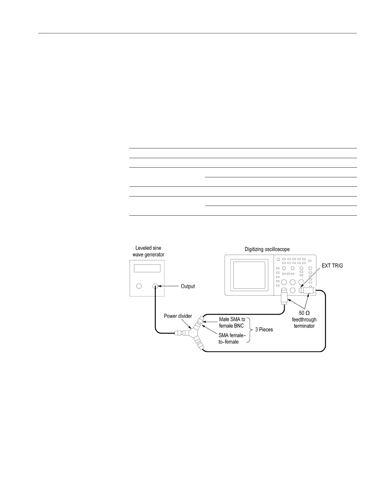
2. Connect the oscilloscope to the leveled sine wave generator as shown in the
following figure, using channel 1 and Ext Trig.
3. Set the oscilloscope Vertical Scale (volts/division) to 100 mV/div.
4. Set the oscilloscope Horizontal Scale (seconds/division) to 25 ns/div.
5. Set the leveled sine wave generator frequency to 10 MHz.
6. Set the sine wave generator o utput level to approximately 300 mV
p-p
into the
power splitter. This is about 200 mV
p-p
on channel 1 of the oscilloscope.
The Ext Trig input will also be receiving approximately 200 mV
p-p
.Small
deviations from the nominal 200 mV
p-p
oscilloscope display are acceptable.
TDS2000C Series Oscilloscope Service Manual 4–9
 Loading...

