Maintenance
TDS3000B Series Service Manual
6-13
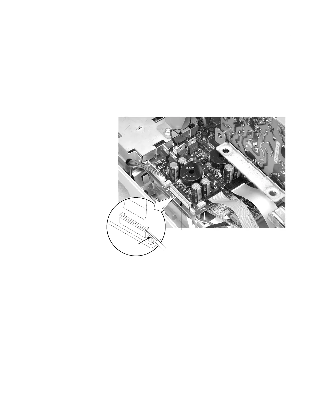
7. C arefully open the disk drive flex cable main board connector J800 and
disconnect the disk drive flex cable from the main board. See F i gure 6--5.
The disk drive is shown removed t o provide a better view of the position of
the main board disk drive flex cable connector J800.
8. Lift the disk drive out of the oscilloscope front panel chassis. Do not remove
the clear tape that holds the flex cable onto the disk drive chassis unless you
are replacing either the disk drive or the flex cable.
Disk drive
connector J800
Screwdriver
Figure 6- 5: Main board disk drive flex cable connector J800
Installation. Use this procedure to i nstall the disk drive, communication module
guide, feet, rear case, and communication module cover.
1. Place the oscilloscope face down on soft surface (such as an anti-static mat),
with the bottom facing you.
2. Install the communication module guide into the chassis. Make sure that the
four pins on the module guide align with the four holes on the m ain board.
Gently lift the rear chassis and insert the small tab i n the chassis slot.
 Loading...


