TDS3000C Series S ervice Manual
2-1
Theory of Operation
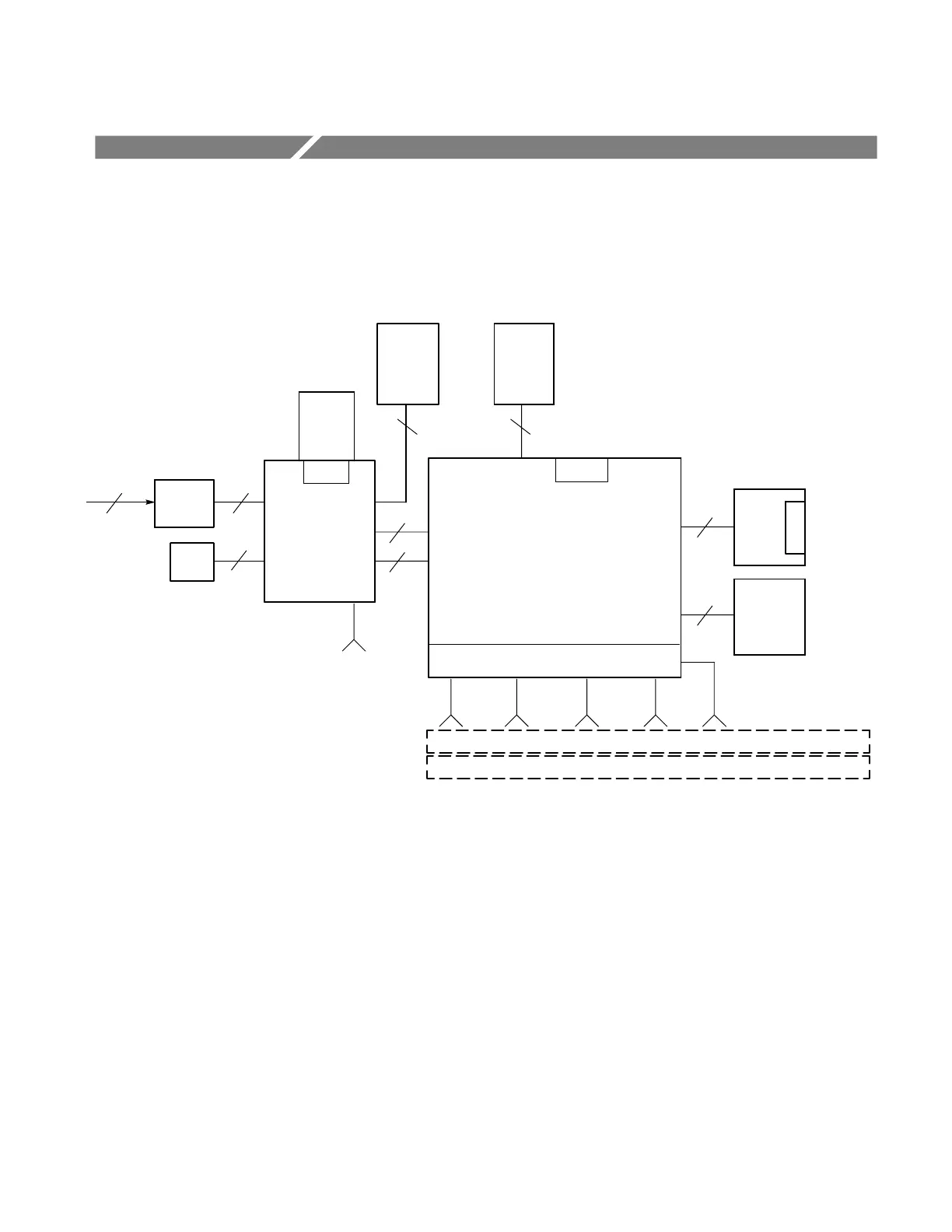
This chapter describes the electrical operation of the oscilloscope to the module
level. Figure 2--1 shows the oscilloscope module interconnections.
Power
supply
Battery bd
Main board
J500
J700
Front
panel
Input ports for
application
modules
J900
Attenuator circuit
Display
back light
inverter
power
LCD
Display
Ch 1
Ch 1
Ch 2
Ch 2
Ch 3
EXT
Ch 4
2-channel oscilloscopes
Battery
pack
J805
Front panel
USB Flash
Drive port
Fan
AC Line
4-channel oscilloscopes
J150
J180
J200
J170
J120
J910
J100
EXT
Ethernet
connector
Comm. module
connector
J860
J700
Figure 2- 1: TDS3000C series block diagram
Power Supply
The power supply converts AC line voltage to 15 VDC to power all internal
circuits. It also supplies power to charge the optional battery pack.
 Loading...