Theory of operation
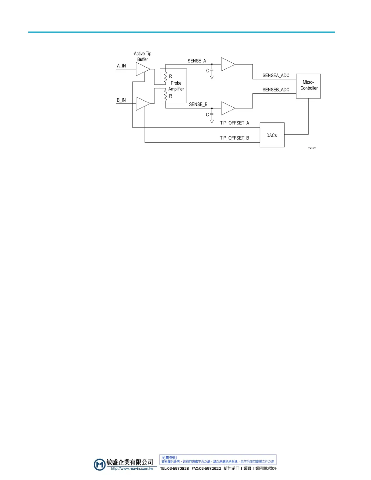
Figure 12: Simplified Auto Offset circuitry
The A and B input signals are buffered by the active probe tip buffer amplifier and
passed down the probe main cable assembly into the comp box probe amplifier
input pins. The A and B input signals are picked off inside the probe amplifier
with large v alue resistors and output to an averaging filter capacitor as Sense_A
and Sens
e_B signals. These sense signals are buffered by a pair of unity gain
amplifiers and passed to the comp box microcontroller ADC conversion inputs.
The converted sense signals are transmitted to the oscilloscope when requested by
an Auto Offset cycle, where they are processed by the oscilloscope according to
the selected Auto Offset mode. The processed mean value or individual A and
B offset values are sent back to the probe microcontroller, which drives the tip
offse
t DAC signals accordingly.
20 P7700 Series TriMode Probes Technical Reference

 Loading...


