24V OUTPUT OPERATION JP1 (terminals 5 and 6)
Before making the connections, decide whether to fit JP1, which modifies operation
ofthe 24V output(terminals 5and6).
- With JP1 fitted in the ON position, the output is always active and can be used to
powerauxiliarydevicesand/orphotocells.
- With JP1 fitted in the Standby position the photocells powered using this output
are switched off at the end of a complete cycle. This set-up reduces the power
drawdownand considerably extends the working life oftheinfrared transmitter.
GB
23
1
32
22
26
18
19
20
17
6
8
14 13 1116
9
10
5
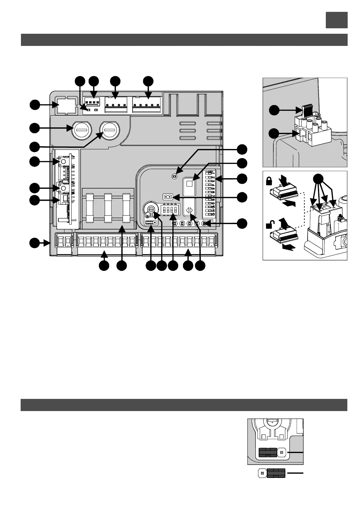
CONTROL UNIT - DESCRIPTION OF PARTS
1)
2)
3) 24V power supply connector
4) Motor + encoder connector
5) Programming LED (LD1)
6) Programming and Stop button
7) Function dip-switches
8) ECU reset. Short-circuiting the 2 pins for a moment is
equivalent to cutting off and restoring the power supply.
9) Input LEDs (on = input closed)
10) Step-by-step operation button
11) Input terminal board
12) Safety device disabling dip-switches
13) Motor force adjustment trimmer
Limit switch sensor LED
Magnetic limit switch sensor connector
14) Photocell manual power supply activation jumper JP1
15) Spare fuses
16) Output terminal board
17) Radio antenna input terminal board
18) OC2 receiver connector
19) OC2 programming key 2 (optional)
20) OC2 programming key 1 (P/P “step-by-step”)
(optional)
21) Motor fuse (16A fast)
22) Auxiliary devices and ECU power supply fuse (2A fast)
23) Programmer connection
24) 230V mains power fuse (T 2A)
25) 230V mains power terminal board
26) Snap connection for ECU
Fig. L
4
12
21
7
15
1
ON
2 3 4
ON
Stand-by
24
25
I
I
II
II
JP1
38
 Loading...