GB
ELECTRIC CONNECTIONS
Make sure that the mains power supply has been disconnected and make the electrical connections.
Take care when stripping cables not to reduce the insulation between terminals or other metal parts.
Ensure that polarities are correct.
After making the connections, check the tightness of screw terminals once more.
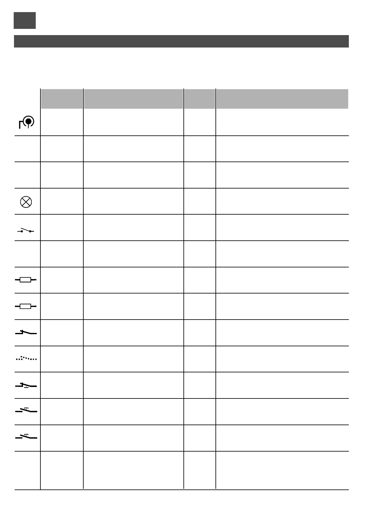
Radio antenna input
Auxiliary device power supply
output
Photocell power supply output (*)
Flasher output
Contact with selectable function
SLAVE command output
Sensitive edge input
tripping during CLOSING
Sensitive edge input
tripping during OPENING
Photocell contact input
Input with selectable function
Stop command input
Pedestrian command input
Step/step command input
Power supply
1
2
Braid
Control
3
4
(+)
(-)
5
6
(+)
(-)
7
8
(+)
(-)
9
10
11
12 (com)
13
12 (com)
14
12 (com)
15
12 (com)
16
17
20 (com)
18
20 (com)
19
20 (com)
21
23
(L)
22 (GND)
(N)
Function / DeviceTerm. n.
/
/
/
/
/
/
/
/
/
/
/
/
/
/
/
24dc/1A
24dc/1A
24dc/1A
/
/
8K2/NC
8K2/NC
NC
/
NC
NA
NA
230/2A
V/I max
Connection only necessary with receiver OC2 active.
Use aerials for frequency 433 MHz (50 Ohm)
Make sure the polarity is correct
With JP1 on Standby, power is only present during
the working cycle.
Power is always present with JP1 on ON.
Switches on with motor in motion.
See part. 7 fig. L, functions 10 and 11.
For systems with 2 synchronised control units;
connect this output to the Jolly input of the Slave
Input enabled during closing. Connect 8K2 edges or an NC
contact with8K2 resistance in series (Fig. O).
Ifnot used(terminalfree), set dip-switch 1of item 12 to ON
Input enabled during opening. Connect 8K2 edges or an NC
contact with8K2 resistance in series (fig. O).
Ifnot used(terminalfree), set dip-switch 2of item 12 to ON
Reverses direction during closure.
If not used, set dip-switch 3 of item 12 to ON
See settings of dip-switches 3 and 4 of item 7
Blocks all functions.
If not used, set dip-switch 4 of item 12 to ON
The gate opens partially for a programmable time
(see “pedestrian opening programming” page 43).
See settings of dip-switches 1 and 2 of item 7
Connect to 230 V line.
Notes
24V
24V
FT
na
8K2*
8K2*
39
 Loading...