T1
T2
− MIC +
LS
− MIC +
LS
1
4
7
*
2
5
8
0
3
6
9 i
#
+
\
\
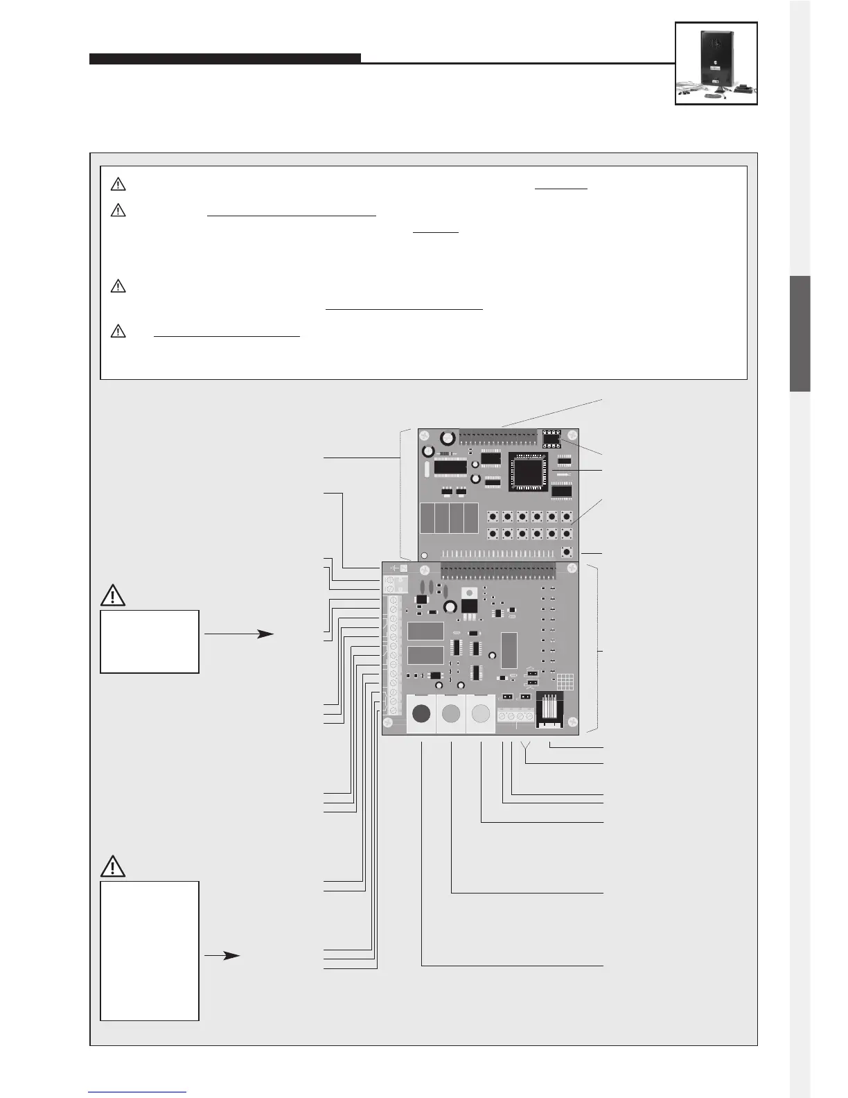
+MLM C +MLM B
MLM A
red blue yellow
EEPROM
Master processor
Internal
configuration and
dialling keyboard
Earth
Main board
Connection board
Dial pad
Loudspeaker
Microphone
MLM A
= main MLM
inside the car
MLM B
= additional MLM
on top of the car
MLM C
= additional MLM
under the car
Telephone ‘ON’
Buttons
Make or break contacts may
be used as nonlocking buttons
T1 button
Common contact
T2 button
Note: The button
inside the car must be
connected to the T2
terminal.
+
–
yellow
blue
red
Program phone number
with configuration step 22
Program phone number
with configuration step 23
Program phone number
with configuration step 24
Note:
The board’s connectors are labelled in German:
While MLM and LS have the same meaning as
in English (i.e. microphone/loudspeaker module
and loudspeaker), T1 and T2 refer to button 1 and
button 2 (German ‘Taste’).
Additional power supply
12 V DC=
potential-free voltage, e.g.
provided by BNOS UPS (only
required for special functions)
–
+
Telephone line
analogue direct exchange
line or PBX extension.
a wire
b wire
Relay 1
Relay contact rating:
60 VA 24 W max.
0.5 A 120 V AC or 1 A 24 V DC
NC
Com.
NO
Relay 2
Relay contact rating:
60 VA 24 W max.
0.5 A 120 V AC or 1 A 24 V DC
NC
Com.
NO
Alarm input
Alarm condition is
active while voltage is
applied
6 to 24 V DC=
–
+
Connector for
electronics extensions
featuring a voice-
announcement facility,
a clock or a display
Connect shield for
microphone and
buttons to –12 V,
not to earth!
Standard = ‘make
contact’; if button
is to be used as a
‘break contact’, the
configuration must
be changed (see
comprehensive
technical manual;
available as PDF on
the Internet).
Distance of the loudspeaker, microphone and buttons from the basic unit: 25 m max.
Buttons must not hav
e a common return wire. To connect the basic electronics package with the user-interface
elements (loudspeaker, microphone and buttons) a shielded
cable must be used. IY-ST-Y or AY-ST-Y. Connect
shield to –12 V terminal (see also Seite 2). Mount dial pad at a distance of 25 m max. (use Behnke patch cable
for connecting the dial pad).
In order to connect MLM A to C (microphone/loudspeaker modules = user units comprising loudspeaker, micro-
phone and button), you should use original Behnke patch cables
– see also page 10.
The integrated add-on amplifier (1 W) can only be activated for MLM A. The corresponding configuration steps can
be found in our comprehensive technical manual (available as PDF on the Internet – see also note on page 2).
ENGLISH
 Loading...