5
2
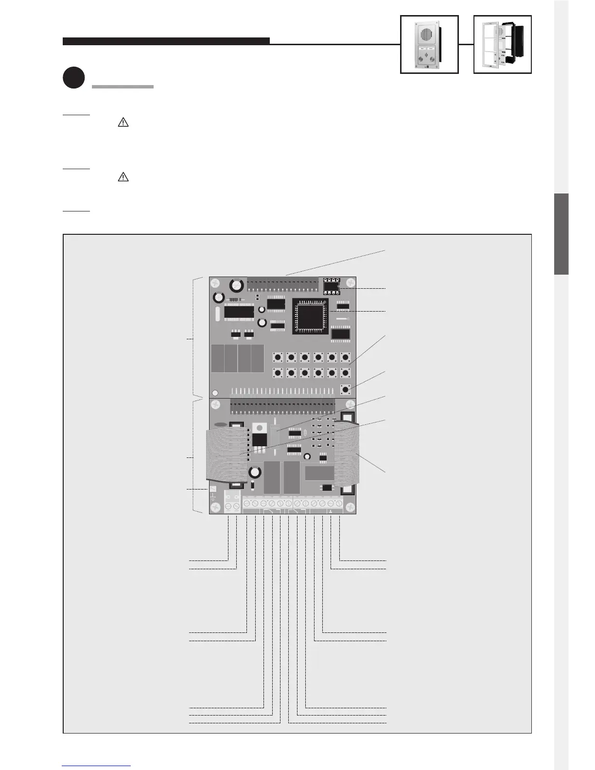
Connection
Step 1: Connect door opener to relay 1, if required.
Relay = voltage-free contact = only operates the door opener, without supplying it with electric energy;
the door opener requires its own power supply! Relay 2 is available for further switching functions (see
comprehensive technical manual; avalailable as PDF on the Internet).
S
tep 2: Connect 12 V DC, if required (potential-free – use Behnke plug-in power supply 20-9500).
Only required for: illumination, camera, integrated heating, integrated add-on amplifier;
not required for: telephone operation, including all functions.
S
tep 3: Connect telephone line (a/b line from analogue PBX extension or analogue direct exchange line) => a long
beep signals the telephone’s operational readiness.
12345
∗
67890#
∗
T
E
L
#
Telefonbau Behnke GmbH
TEL
a / b
– 12 V +
REL. 1 REL. 2
+ ALARM – VIDEO
Connector for electronics
extensions
EEPROM
Master processor
Internal configuration
and dialling keyboard
Heating resistor
Connecting cable for
illumination
Connecting cable for
modules
Video output
Alarm input
Relay 2
Additional
power supply
Telephone line
Earth
only wired in connection with
a module with camera
Alarm condition is active while
voltage is applied
Relay contact rating:
60 VA 24 W max.
0.5 A 120 V AC or 1 A 24 V DC
6 to 24 V DC
Relay 1
Relay contact rating:
60 VA 24 W max.
0.5 A 120 V AC or 1 A 24 V DC
12 V DC
potential-free voltage,
e.g. from Behnke plug-in
power supply
analogue direct
extension line or
PBX extension
Main board
Connection board
a wire
b wire
–
+
NC
Com.
NO
Video signal
Video earth
–
+
NO
Com.
NC
(only needed for modules with
illumination)
Telephone ‘ON’
featuring a voice-announcement
facility, a clock or a display
 Loading...