Resource
nRSTOUT TPS65941213-Q1
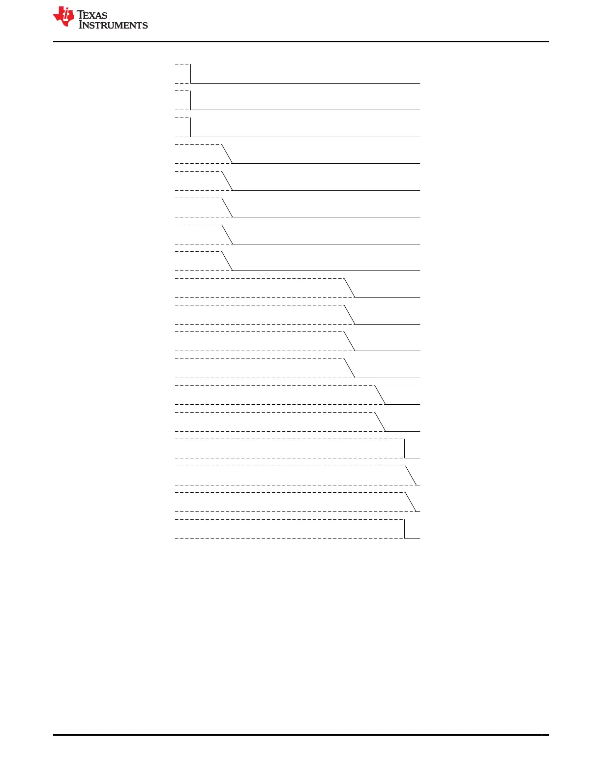
PMIC Delay Diagram Total Delay Rail Name
0 us H_MCU_PORz_1V8
nRSTOUT_SOC TPS65941213-Q1 0 us H_SOC_PORz_1V8
BUCK3 Monitor TPS65941213-Q1 500 us mVDD_MCUIO_3V3
LDO3 TPS65941213-Q1 2500 us VDD_DLL_0V8
BUCK123 TPS65941213-Q1 2500 us VDD_CPU(AVS)
BUCK4 TPS65941213-Q1 2500 us VDD_MCU_0V85
BUCK5 TPS65941213-Q1 3000 us VDD_PHY_1V8
LDO2 TPS65941213-Q1 500 us VDD_MCUIO_1V8
LDO4 TPS65941213-Q1 500 us VDA_MCU_1V8
GPIO9 TPS65941213-Q1 3500 us EN_MCU3V3IO_LDSW
BUCK5 TPS65941111-Q1 500 us VDD_RAM_0V85
LDO3 TPS65941111-Q1 500 us VDD_IO_1V8
BUCK1234 TPS65941111-Q1 2500 us VDD_CORE_0V8
LDO4 TPS65941111-Q1 3000 us VDA_PLL_1V8
LDO1 TPS65941111-Q1
3500 us VDD_SD_DV
LDO2 TPS65941111-Q1 3500 us VDD_USB_3V3
GPIO11 TPS65941111-Q1 3500 us EN_3V3IO_LDSW
EN_DRV TPS65941213-Q1 0 us EN_DRV
Figure 6-13. TO_RETENTION when I2C_7 is high in both PMICs
At the end of the sequence, both PMICs set the LPM_EN and clear the CLKMON_EN and AMUXOUT_EN.
The TPS65941213 device also performs an additional 16 ms delay based upon the contents of the register
 Loading...