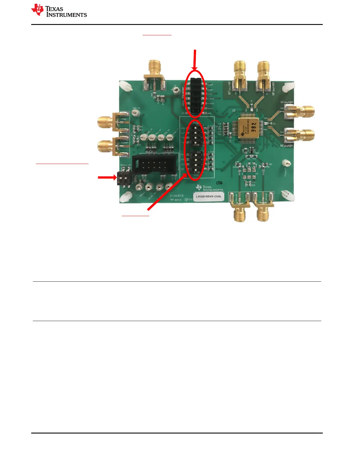
Readback/Lock Detect
Set both switches high to
connect Readback to the
programmable header and
so that a locked status will
light the LED
Vcc Headers
Top 6 headers should be placed to power each
individual Vcc Pin. The bottom header can be left off
as this is for GND
FS Switches
All 8 switches should be all the way to the left.
This is for the default of SPI mode
Figure 9-2. EVM Jumper and Switch Positions
10 Revision History
NOTE: Page numbers for previous revisions may differ from page numbers in the current version.
Changes from Revision * (November 2018) to Revision A (August 2022) Page
• Changed U1 description in Table 7-1 from: LMX2615HBD, HBD0064A (CFP-64) to: LMX2615-SP................. 9
• Changed U1 part number in Table 7-1 from: LMX2615HBD to: LMX2615W-MPR............................................ 9
• Changed Item 32 designator in Table 7-1 from: S1, .., S4 to: H1, …, H4........................................................... 9
• Changed the R32 quantity (Qty) in Table 7-1 from 1 to 0................................................................................... 9
• Removed U2 from Table 7-1 ..............................................................................................................................9
www.ti.com Revision History
SNAU218A – NOVEMBER 2018 – REVISED AUGUST 2022
Submit Document Feedback
LMX2615EVM-CVAL Wideband 15-GHz Synthesizer 15
Copyright © 2022 Texas Instruments Incorporated

 Loading...


