1 Evaluation Board Setup and Description
SPACER
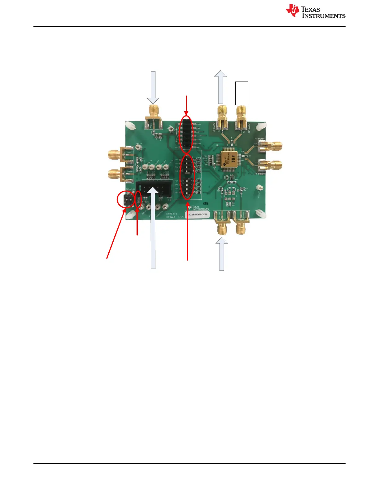
+3.3 V
To Spectrum
Analyzer
50 :
Termination
100 MHz Input
Reference
Lock Detect
LED
Readback/
Lock Detect
Selector
Switch
Reference Pro
SPI interface
FS Switches
Power
Jumpers
Figure 1-1. LMX2615EVM Setup and Description
1. Power:
a. Set power supply to 3.3 V with 600-mA current limit and connect to V
CC
SMA.
2. Input Signal
a. The EVM is designed for a 100-MHz input reference that should be connected to the OSCin SMA. Some
of the options for this could be a signal generator, the 100 MHz output from the Reference Pro board, or
a very clean signal source such as the Wenzel 501-4623G ultra-low phase noise 100 MHz reference
3. Programming Interface:
• Reference Pro will provide SPI interface to program LMX2615. If using this, Connect USB cable
from laptop or PC to USB port in Reference Pro. This provides power to Reference Pro Board and
communication with TICS GUI
• The other option is to use the dip switch on the board to use Pin mode.
4. Output:
a. Connect RFoutAP to a phase noise analyzer and connect a 50-Ω terminator to RFoutAM.
Evaluation Board Setup and Description www.ti.com
2 LMX2615EVM-CVAL Wideband 15-GHz Synthesizer SNAU218A – NOVEMBER 2018 – REVISED AUGUST 2022
Submit Document Feedback
Copyright © 2022 Texas Instruments Incorporated

 Loading...


