www.ti.com
Functional Description
2.1.6.3 Breadboard Connection
The breadboard adapter section of the board is a set of 98 holes on a 0.1 inch grid. Properly combined with a pair of right angle headers, the
entire Connected LaunchPad can be plugged directly into a standard 300 mil (0.3 inch) wide solder-less breadboard. The right angle headers and
breadboard are not provided with this kit. Suggested part numbers are Samtec TSW-149-09-L-S-RE and TSW-149-08-L-S-RA right angle pin
headers and Twin industries TW-E40-1020 solder-less breadboard. Samtec TSW-149-09-F-S-RE and TSW-149-09-F-S-RA may be substituted.
A detailed explanation of how to install the headers is available on the TI LaunchPad Wiki or at
http://users.ece.utexas.edu/~valvano/EE345L/Labs/Fall2011/LM3S1968soldering.pdf.
Nearly all microcontroller signals are made available at the breadboard adapter holes (X11). These signals are grouped by function where
possible. For example, all EPI signals are grouped on one side of the connector. Many of the analog signals are grouped near VREF, and UART,
SSI and I2C signals are grouped by peripheral to make expansion and customization simpler.
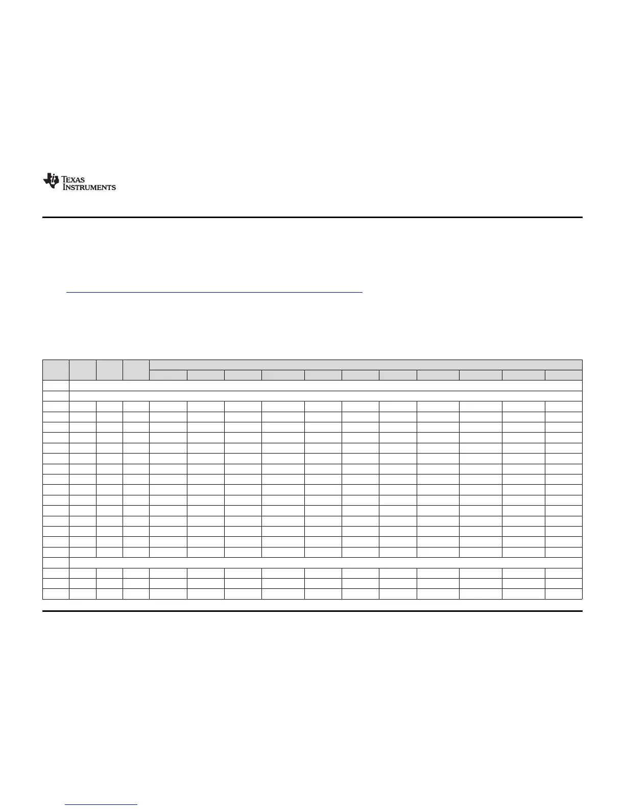
Table 2-3 and Table 2-4 show the GPIO pin and signal muxing for the X11 breadboard adapter pads.
Table 2-3. X11 Breadboard Adapter Odd-Numbered Pad GPIO and Signal Muxing
Digital Function (GPIOPCTL Bit Encoding)
MCU
Pin Port Analog
PIN
1 2 3 5 6 7 8 11 13 14 15
1 3V3
3 GND
5 PB4 121 AIN10 U0CTS I2C5SCL - - - - - - - - SSI1Fss
7 PB5 120 AIN11 U0RTS I2C5SDA - - - - - - - - SSI1Clk
9 PH0 29 - U0RTS - - - - - - - - - EPI0S0
11 PH1 30 - U0CTS - - - - - - - - - EPI0S1
13 PH2 31 - U0DCD - - - - - - - - - EPI0S2
15 PH3 32 - U0DSR - - - - - - - - - EPI0S3
17 PC7 22 C0- U5Tx - - - - - - - - - EPI0S4
19 PC6 23 C0+ U5Rx - - - - - - - - - EPI0S5
21 PC5 24 C1+ U7Tx - - - - RTCCLK - - - - EPI0S6
23 PC4 25 C1- U7Rx - - - - - - - - - EPI0S7
25 PA6 40 - U2Rx I2C6SCL T3CCP0 USB0EPEN - - - - SSI0XDAT2 - EPI0S8
27 PA7 41 - U2Tx I2C6SDA T3CCP1 USB0PFLT - - - USB0EPEN SSI0XDAT3 - EPI0S9
29 PG1 50 - - I2C1SDA - - M0PWM5 - - - - - EPI0S10
31 PG0 49 - - I2C1SCL - EN0PPS M0PWM4 - - - - - EPI0S11
33 PM3 75 - - - T3CCP1 - - - - - - - EPI0S12
35 GND
37 PM2 76 - - - T3CCP0 - - - - - - - EPI0S13
39 PM1 77 - - - T2CCP1 - - - - - - - EPI0S14
41 PM0 78 - - - T2CCP0 - - - - - - - EPI0S15
13
SPMU365A–March 2014–Revised March 2014 Hardware Description
Submit Documentation Feedback
Copyright © 2014, Texas Instruments Incorporated

 Loading...


