+3V3
+5V
GND
0.1uF
2.2uF
0.1uF
GND
330
GND
100k
4.87k 1%
GND
GND
0.1uF 1.0uF 2.2uF
0.1uF 0.1uF 0.1uF 0.1uF
GND
0
0
GND
1M
SWITCH_TACTILE
12pF
12pF
10k
0.1uF
12pF 12pF
SWITCH_TACTILE
GND
MOUNT-HOLE3.2
MOUNT-HOLE3.2
GND
GND
GND
GND GND
TPS2052B_DRB_8
+5V
10k
100k
GND
51
0.1uF
GND
+3V3
100k
TPS73733_DRV_6
OMIT
2k
MOUNT-HOLE3.2
100
CRYATL_32K_SMD
C19
C20
C21
D0
R9
R17
TP3
R25
C4 C14 C15
C40 C41 C42 C43
TP9
TP10
TP11
TP12
R39
TP13
R41
R42
RESET
C44
C45
NC2
P$2
NC4
P$4
OSC0
P$1
OSC1
P$3
R44
C46
C47 C48
WAKE
H4
H6
*EN1
3
*EN2
4
*OC1
8
*OC2
5
EPAD
9
GND
1
IN
2
OUT1
7
OUT2
6
VIA
V
VIA
V_2
VIA
V_3
VIA
V_4
VIA
V_5
VIA
V_6
U4
JP1
1 2
3 4
5 6
JP2
1
2
JP3
1
2
R35
R36
TP8
R38
C3
R26
EN
4
EPAD
7
GND
3
IN
6
NC
5
NR/FB
2
OUT
1
VIA
V
VIA
V_2
U5
R48
R49
H1
R51
HIB
P$65
RESET
P$70
WAKE
P$64
EN0RXIN
P$53
EN0RXIP
P$54
EN0TXON
P$56
EN0TXOP
P$57
GND
P$17
GND
P$48
GND
P$55
GND
P$58
GND
P$80
GND
P$114
GNDA
P$10
OSC0
P$88
OSC1
P$89
RBIAS
P$59
VBAT
P$68
VDD
P$7
VDD
P$16
VDD
P$26
VDD
P$28
VDD
P$39
VDD
P$47
VDD
P$51
VDD
P$52
VDD
P$69
VDD
P$79
VDD
P$90
VDD
P$101
VDD
P$113
VDD
P$122
VDDA
P$8
VDDC
P$87
VDDC
P$115
VREFA+
P$9
XOSC0
P$66
XOSC1
P$67
P$1
P$1
P$2
P$2
Y3
TARGET_VBUS/3.2C
TARGET_VBUS/3.2C
DEBUG_VBUS/6.4A
EN0RXI_N
EN0RXI_P
EN0TXO_N
EN0TXO_P
RBIAS
WAKE/3.3D
MCU_3V3/6.2A
MCU_3V3/4.1A
VBUS
VBUS
VBUS
PQ4/3.4D
PD6/3.2B
TARGET_RESET/3.2D
A
B
C
D
E
A
B
C
D
E
1 2 3 4 5 6
Y1
25Mhz
U1G$2
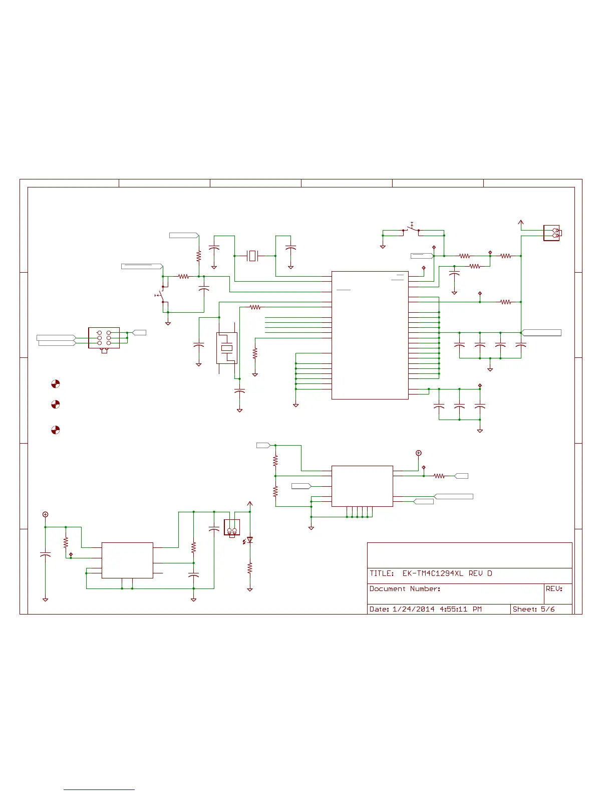
Power Control Jumper:
1) To power from Debug install jumper on pins 5 - 6
2) To power from Target USB install jumper on pins 3 - 4
3) To power from BoosterPack 5V install jumper on pins 1 - 2
This is also the off position if BoosterPack does not
supply power
When powered from BoosterPack TPS2052B does not
provide current limit protection.
When powered by BoosterPack, USB host mode does not
supply power to connected devices
Primary 3.3V regulator
Disconnect JP3 to power device from 3V3 BoosterPack
JP2 can be used to measure MCU current
consumption with a multi-meter.
TPS2052B provides current limit for main 5V power.
Also provides power switching for USB host/OTG modes
For Host/OTG:
PD6 configured as USB0EPEN peripheral function.
PQ4 configure as individual pin interrupt. Indicates
power fault on the USB bus. USB0PFLT peipheral pin
not available due to pin mux and use on BoosterPacks.
USB Host mode does not supply power to devices
when powered from a BoosterPack
For Applications that do not use USB:
Configure PD6 as input with internal pull-down
enabled. Turns off power to TARGET_VBUS
R38 and C3 Used to meet
VBAT rise time requirements
R41 may be removed and precision
reference applied to TP13

 Loading...


