User’s Guide
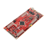
TPS65994 EVM User Guide
ABSTRACT
This document is the user guide for the TPS65994 Evaluation Module. The TPS65994 EVM allows for evaluation
of the TPS65994 IC (WCSP and QFN package) functionality as part of a stand-alone testing kit and for
development and testing of USB Type-C
™
and Power Delivery (PD) end products.
Table of Contents
1 About this Manual...................................................................................................................................................................3
2 Items Required for Operation................................................................................................................................................ 3
3 Introduction.............................................................................................................................................................................3
4 Setup........................................................................................................................................................................................4
4.1 Switch, Push Button, Connector, and Test Point Descriptions........................................................................................... 4
4.2 LED Indicators Description.................................................................................................................................................9
5 Tiva USB to I2C Bridge Support Integration...................................................................................................................... 10
5.1 Flash Application Firmware to EEPROM......................................................................................................................... 10
5.2 Entering Debug Mode...................................................................................................................................................... 13
6 Using the TPS65994EVM......................................................................................................................................................17
6.1 Powering the TPS65994EVM.......................................................................................................................................... 17
6.2 Firmware Configurations.................................................................................................................................................. 17
7 Connecting the EVM.............................................................................................................................................................18
7.1 Connecting to Various Devices........................................................................................................................................ 18
8 Debugging the EVM..............................................................................................................................................................19
8.1 Connection Not Established.............................................................................................................................................19
8.2 Resetting Behavior...........................................................................................................................................................19
9 TPS65994EVM Schematics.................................................................................................................................................. 20
10 TPS65994EVM Board Layout.............................................................................................................................................27
11 TPS65994EVM Bill of Materials..........................................................................................................................................32
12 TPS65994QFNEVM Schematics........................................................................................................................................ 36
13 TPS65994QFNEVM Board Layout..................................................................................................................................... 44
14 TPS65994QFNEVM Bill of Materials..................................................................................................................................49
15 Revision History................................................................................................................................................................. 53
List of Figures
Figure 4-1. TPS65994 Power Path Jumper Configuration.......................................................................................................... 4
Figure 4-2. ADCIN1 and ADCIN2 Configuration Schematic........................................................................................................5
Figure 4-3. Barrel Jack (J2) Schematic....................................................................................................................................... 5
Figure 4-4. USB Type-C™ Receptacle (J3_PA) Schematic........................................................................................................ 6
Figure 4-5. USB Type-C™ Receptacle (J3_PB) Schematic........................................................................................................ 6
Figure 4-6. USB Micro-B Receptacle (J6) Schematic..................................................................................................................7
Figure 4-7. Aardvark Connector (J9) Schematic......................................................................................................................... 7
Figure 4-8. Debug Header (J4) Schematic.................................................................................................................................. 8
Figure 4-9. Debug Header (J5) Schematic.................................................................................................................................. 9
Figure 5-1. Application Customization Tool............................................................................................................................... 10
Figure 5-2. I/O Config Register.................................................................................................................................................. 11
Figure 5-3. Flash Project to EEPROM (I2C)..............................................................................................................................12
Figure 5-4. USB to I2C/SPI Adapter Settings............................................................................................................................ 13
Figure 5-5. I2C Addresses.........................................................................................................................................................14
Figure 5-6. Addressing range.................................................................................................................................................... 15
Figure 5-7. Transmit Source Capabilities...................................................................................................................................16
Figure 9-1. TPS65994EVM Block Diagram............................................................................................................................... 20
Figure 9-2. TPS65994EVM PD Controller................................................................................................................................. 21
www.ti.com
Table of Contents
SLVUBM1C – JANUARY 2019 – REVISED JANUARY 2021
Submit Document Feedback
TPS65994 EVM User Guide 1
Copyright © 2021 Texas Instruments Incorporated


 Loading...