2 EVM Setup and Quick Start Guide
Default EVM Configuration lists the default configuration.
Table 2-1. Default EVM Configuration
Parameter Specification
Input Power Supply 4 V to 14V
Operating Temperature 25°C
Switching Frequency 500 kHz
The TPS7H5001-SP can be quickly turned on and run using the connections shown in TPS7H5001-SP
Connections.
Table 2-2. TPS7H5001-SP Connections
Terminal or Test Point Voltage Source
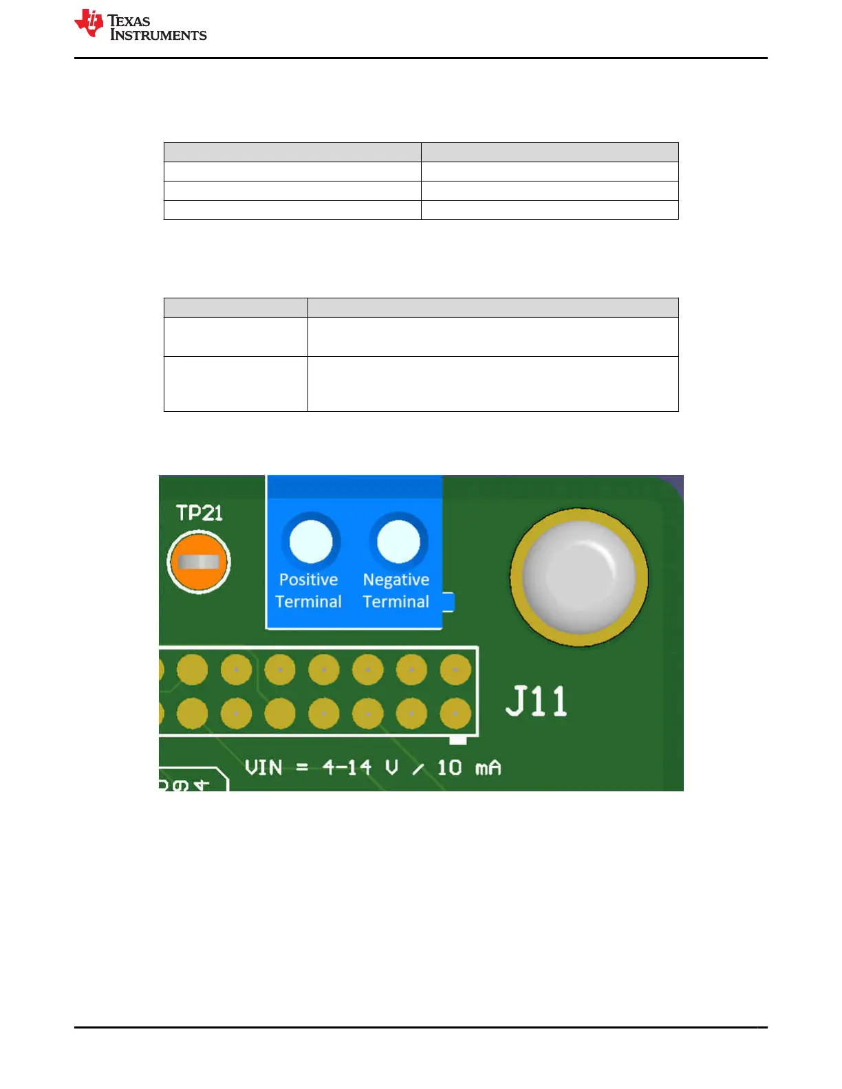
J11 (VIN) 4 to 14 V input at 10 mA, See Positive and Negative Terminal for J11 for
connections
TP9 (COMP) 1 V at < 10 mA (Input range can be –0.3 V to 3.3 V based on the
TPS7H5001-SP Radiation-Hardness-Assured Si and GaN Dual Output
Controller data sheet)
Positive and Negative Terminal for J11 shows which terminal is the positive and negative on J11. Connect the
positive input voltage to the positive terminal and GND to negative terminal.
Figure 2-1. Positive and Negative Terminal for J11
www.ti.com EVM Setup and Quick Start Guide
SLVUBZ8 – JULY 2021
Submit Document Feedback
TPS7H5001-SP Evaluation Module 3
Copyright © 2021 Texas Instruments Incorporated

 Loading...


