41
August ’01 Chapter 2. Electrical Description
2.10.3.11Wake Pattern Waiting Time 'C_WAIT'
If the Wake Pattern check detected no modulation after internal wake-up, it can be assumed
that noise was the reason for activation. A initialization and return to the Standby Mode after
a reasonable waiting time is meaningful. Therefore a counter is loaded with cwait. The
counter counts down using CLKI as source. The resulting waiting time must be adapted to
the Wake-up Times (tWAKE) used in the system. Typically the Wake-up Time is shorter than
10ms. In best case the Identification Device internally wakes up 3 ms after beginning of wake
period. So the Control Unit has to wait at least 7 ms until begin of modulation (see Table 7).
If the Battery Backup function is used, longer Wake-up times will be used. Assuming that
reaction times of more than 200 ms will not be acceptable by the system user and the mini-
mum communication time is 50 ms, the maximum Wake-up Time will be around 150 ms. Be-
cause of the exponential rise behavior, the charge voltage VCL will reach 63% of the
maximum voltage (~3 V) after 30 ms. At this time enough voltage is available at VCCO to
initialize the Microcomputer (~2.5 V). Because the initialization will need some time
WDEEN will not be set before the 30 ms are gone and the Wake Pattern will be received latest
120 ms after start of Wake-up Time.
The Wake Pattern Waiting Time is calculated with the following formula:
twait = cwait / fTX
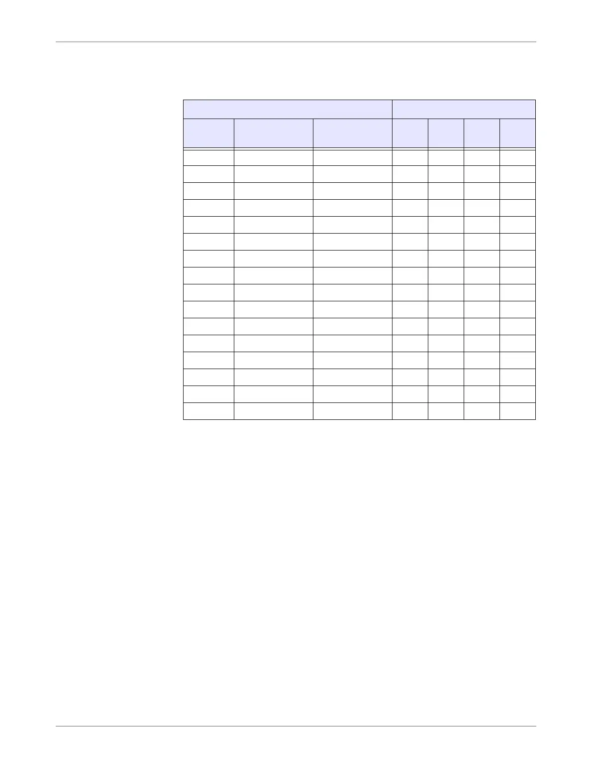
Table 6: Counter Definition for Pulse Position Demodulation
Telegram Duration
DEC ctelegr
ttelegr
nom.[ms]
MSB LSB
0 4096 30.5 0 0 0 0
1 8192 61.0 0 0 0 1
2 12288 91.6 0 0 1 0
3 16384 122.1 0 0 1 1
4 20480 152.6 0 1 0 0
5 24576 183.1 0 1 0 1
6 28672 213.7 0 1 1 0
7 32768 244.2 0 1 1 1
8 36864 274.7 1 0 0 0
9 40960 305.2 1 0 0 1
10 45056 335.7 1 0 1 0
11 49152 366.3 1 0 1 1
12 53248 396.8 1 1 0 0
13 57344 427.3 1 1 0 1
14 61440 457.8 1 1 1 0
15 65536 488.4 1 1 1 1
 Loading...