43
August ’01 Chapter 2. Electrical Description
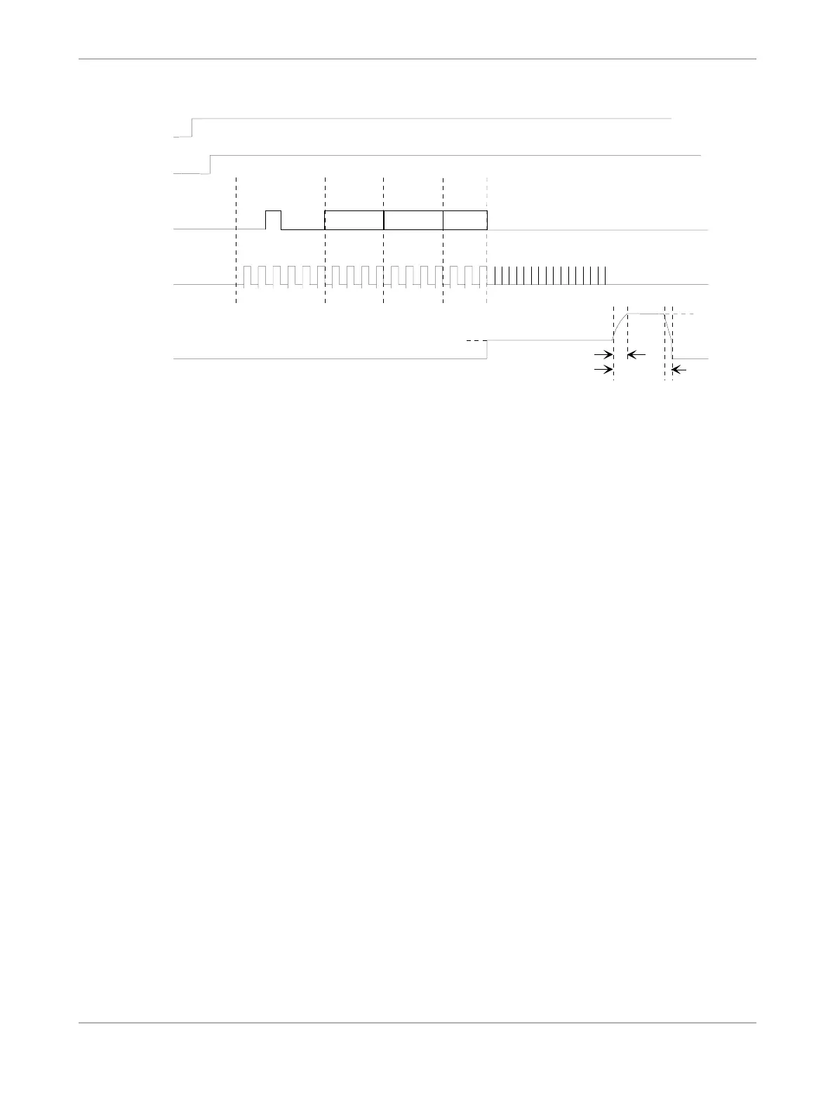
Figure 24: Timing Diagram for Test Mode PTx04
2.10.5 Memory Read
The result of programming function is checked with Read Test Mode PTx07 (see Figure 25).
After shifting in the Test Mode (07hex), the Row and Nibble address, the Tester Unit con-
nected to TDAT must be switched to input. Fifteen TCLK pulses are needed to clock the IC
Control Unit. After nine TCLK pulses the first data bit is already available at output TDAT.
Then additional five clocks are required for the Control Unit. With the negative transition of
the next TCLK, the Tester Unit must store the first data bit. The next three data bits are shifted
with the positive transition of TCLK and should be stored by the Tester Unit at the negative
transitions.
Low at TEN resets the test circuit and TDAT becomes input again.
112345
LSB
VBAT
TDAT
TCLK
TEN
TEST MODE
PTx04
123
DATA
ROW NIBBLE
23
12
tPRG
LSB LSB LSB
tfVPP
trVPP
VBAT
VPP
64431 16
WDEEN
3DTMOD4A.DRW
 Loading...