Creation: 01.31 - 2014
1-1-11
GPU - 406
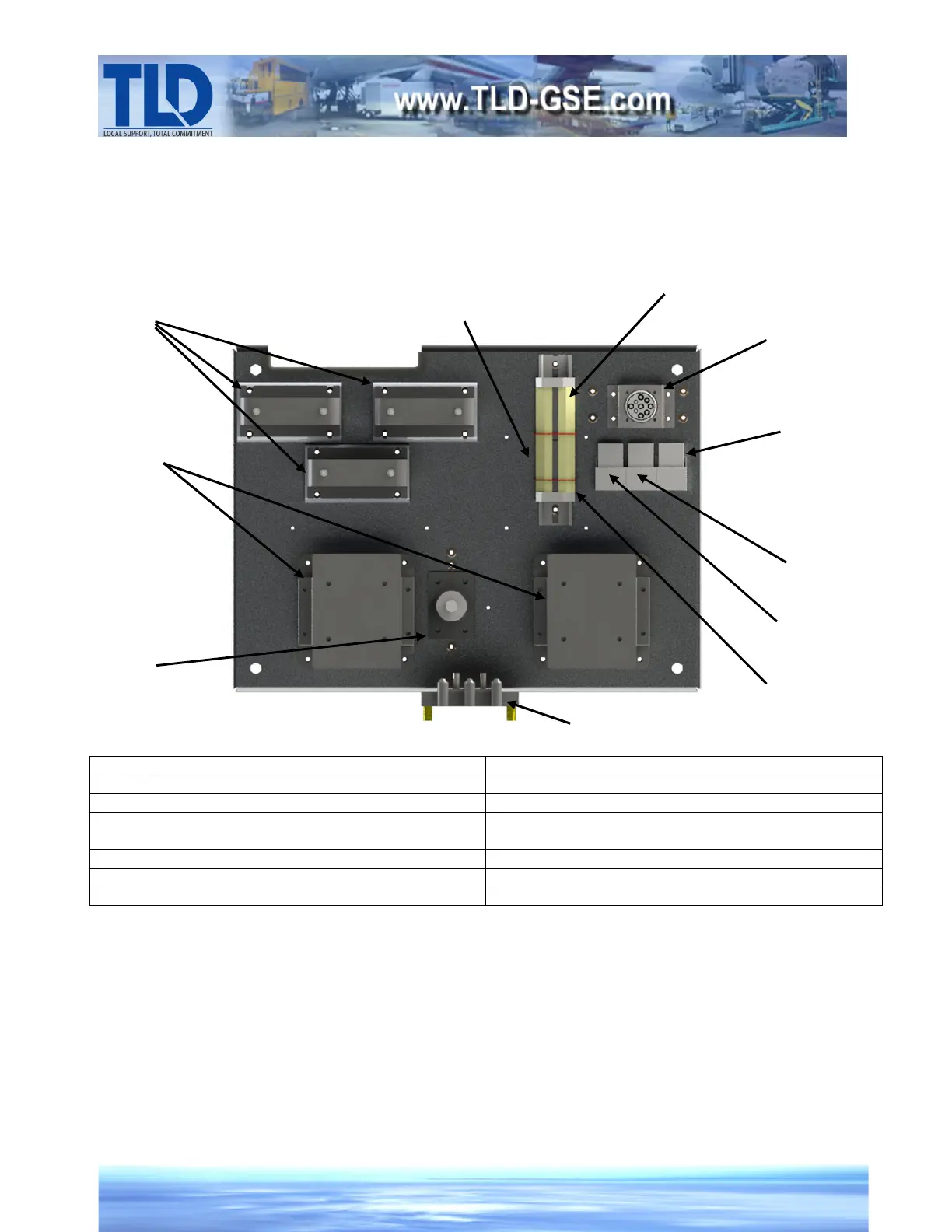
A. Relay Panel Assembly
The relay panel assembly is mounted inside the electrical box on the back wall. The relay panel
provides mounting facilities for engine and generator control and protection relays, 3 current
transformers, and output load contactor(s).
RELAY PANEL
FIGURE 8
1…Current Transformers – T1, T2, T3 8…Engine Running Relay – K3
2…Contactor(s) – K16 (K17 is optional) 9…Key Switch Power Relay – K10
3…Generator Neutral Distribution Block – TB2 10…Low Fuel Relay – K5
4…400Hz Control Signal Terminal Blocks – TB8 (TB10
is optional and not shown)
11…J1939 Data Link Connector – P11
5…Battery Ground Terminal Block – TB5
6…Switched +24V Terminal Block – TB3
7…Battery Power Terminal Block – TB7
8
4
T3
T1
T2
K3
K16
K5
K10
K17
 Loading...