TOPVERT S1 Series
E-
5
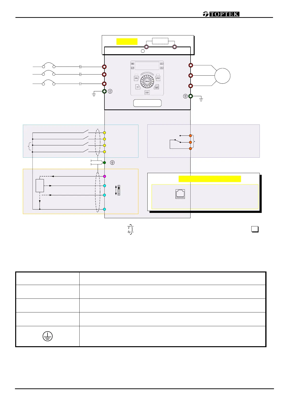
Basic Wiring Diagram
Main Circuit Terminal Explanations
Terminal Symbol Content Explanation
R(L1),S(L2),T(L3) AC line input terminals
U(T1),V(T2),W(T3) Drive output terminals motor connections
/B1, B2⊕
Connections for Braking Resistor (optional)
Refer to Chapter 9 (the selection chart)
Ground terminals, please have these terminals grounded following the
third-type grounding of 230V series and the special grounding of 460V
series within the electrician regulations
Remark: ◎ → Main circuit ○ → Control circuit → Shielded leads & Cable ( ) → Factory default → option
+12V 20mA
0〜10V (20KΩ)
3-Phase
power source
NFB
None Fuse Breaker
AVI
Main circuit
Control circuit
Motor
M
3~
U(T1)
W(T3)
V(T2)
(Frequency Command)
Multi-function
Analog input
R(L1)
M.C.
T(L3)
[ Use R(L1), S(L2) for 1-phase models ]
S(L2)
Multi-function
Digital input
E
Digital/Analog Signal Common
(DI)
(AI)
MI1
MI2
FWD / STOP
(Multi-Step2)
(Multi-Step1)
REV / STOP
FWD
REV
Factory Default
TOPVERT S1
Braking Resistor
Pin assignment :
1: Reserved 2: Reserved
3: GND 4: SG- 5: SG+ 6: +5V
7: Reserved 8: Reserved
87654321
Serial port
Multi-function
Relay output
R1A
R1B
R1C
Contact output 1
(indicates malfunction)
240VAC/2.5A, 120VAC/5A, 24VDC/5A
RS-485 Serial port option kit
4〜20mA (250Ω)
VR : 5〜10 KΩ
B2
B1
+
TDBR
(Option)
(AVI)
ACI
+12V
1
2
3
ACI
COM
(Ry)
 Loading...