3
InstallingtheNewEngine
Partsneededforthisprocedure:
1Engine
4
Setscrew
4Nut
1
Self-tappingscrew
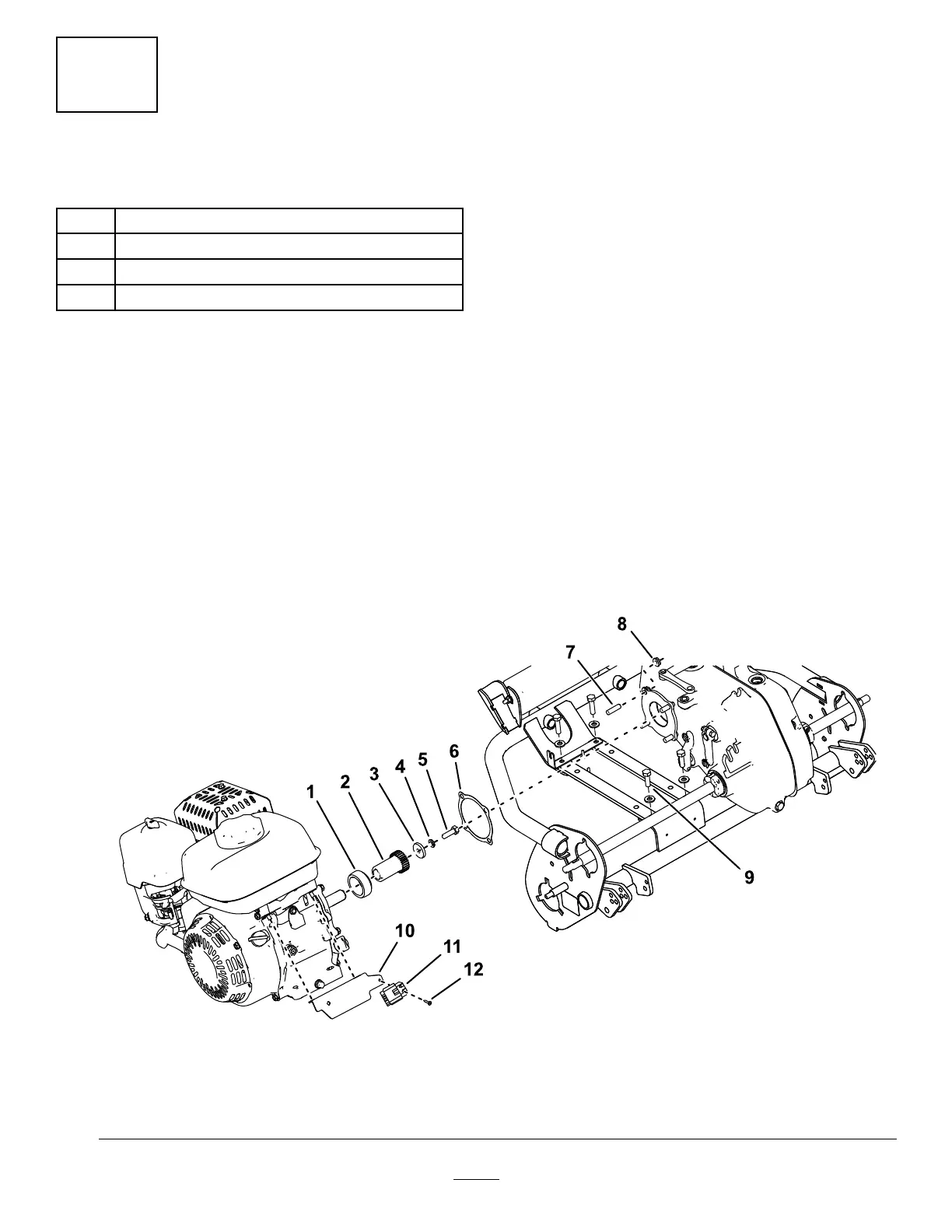
Procedure
1.Applymedium-strengththread-locking
compound(suchasBlueLoctite®242)tothe
threadsofthenewsetscrewsandinstallthem
totheengine(Figure8).
2.Installthepreviouslyremovedengineoutput
shaftcomponentstotheengine(Figure8).
Note:Applyanti-seizecompoundtothekey
andenginedriveshaftbeforeinstalling.
3.Installtheinterlockmoduletothewireharness
bracketwiththeincludedself-tappingscrew
(Figure8).
Note:Thewireharnessbracketisalready
installedontheengine.
4.Installthegearboxgaskettothesetscrewson
thecrankcasecover.
5.Positiontheengineontheenginemountwith
theshaftfacingtowardthegearboxassembly.
6.Slidetheenginetowardthegearboxwhile
guidingthedrivegearintogearboxinputarea.
Note:Thecrankshaftmayhavetobeturnedto
meshtheenginegearteethwiththegearbox
inputgear.
7.Installandnger-tightenthe4angenutsthat
securethegearboxassemblytothesetscrews
ontheenginecrankcasecover.
8.Installthe4previouslyremovedengineboltsand
washersthroughtheengineandenginemount.
9.Securetheenginebyinstalling4nutsonthe
engineboltsfromtheundersideoftheengine
mount.
10.Fullytightentheangenutsthatsecurethe
gearboxassemblytotheengineandthenuts
thatsecuretheenginetotheenginemount.
g274576
Figure8
1.Engineadapter4.Lockwasher
7.Setscrew
10.Wire-harnessbracket
2.Enginegear5.Bolt8.Nut11.Interlockmodule
3.Washer
6.Gearboxgasket
9.Engineboltsandwashers
12.Self-tappingscrew
7
 Loading...


