5
InstallingtheControls
Partsneededforthisprocedure:
1Tractionbracket
1Throttlelever
1
Spring
Procedure
1.Installthenewtractionbrackettothehandle
usingthepreviouslyremovedhardware(Figure
15).
Note:Iftheoriginaltractionbracketwas
attachedtothemachinethrough2holesinthe
handle,orderPartNo.112-9318and110-2415
tocompletetheinstallation.
2.Installthepreviouslyremovedhandleassembly.
Note:Refertothehandleassemblyremoval
andreversethestepsforinstallation.
3.Installthepreviouslyremovedtractionleverand
cablewiththepreviouslyremovedfasteners
(Figure15).
Important:Theinstallationissimilartothe
installationontheremovedbracket;referto
thepreviousremovalinstructions(Figure5).
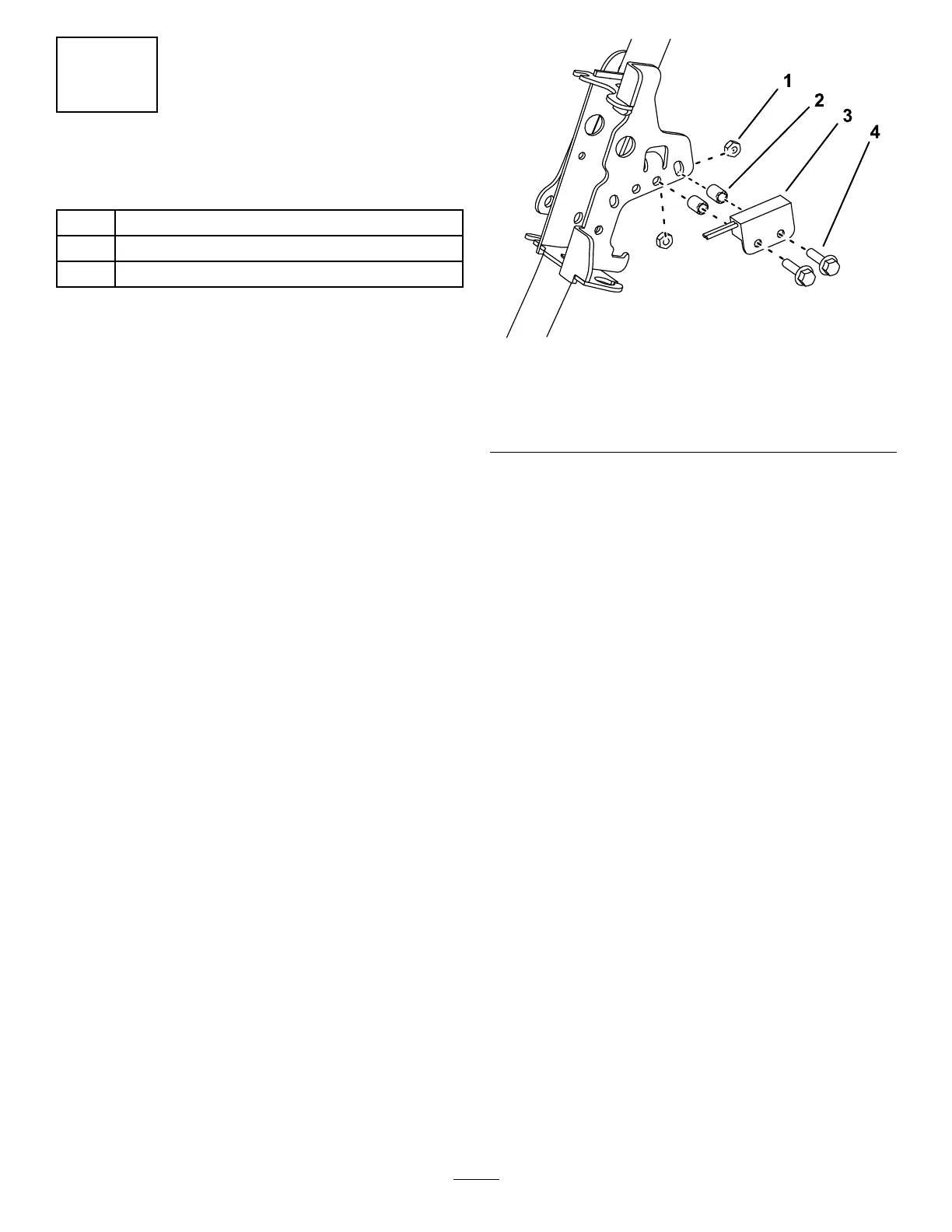
4.Installtheproximityswitchtothetractionbracket
usingthepreviouslyremovedfasteners;ensure
thatthedistancebetweenthetopofthesensor
andthebottomofthetractionhandleiswithin
6/100to9/100inches(Figure11).
Note:Usetherearholesforproximityswitch
installation.
g274781
Figure11
1.Nut
3.Proximityswitch(sensor
up)
2.Spacer
4.Bolt
5.Installandadjusttheinterlockswitchaccording
totheinstructionsinyourOperator’sManual.
6.Installthenewthrottlelevertothetraction
bracketusingthepreviouslyremovedhardware
(Figure15).
9
 Loading...


