downsothatthebartsoverthebaracrossthetop
ofthecuttingunit(Figure12).
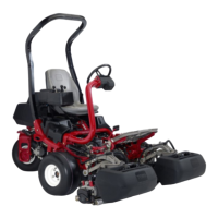
Figure11
1.Latch—closedposition3.Latch—openposition
2.Suspension-armbar
Figure12
1.Suspension-armbar2.Cutting-unitbar
6.Closethelatchesdownandaroundthecutting-unit
barandlocktheminplace(Figure11).
Note:A“click”canbeheardandfeltwhenthe
latchesareproperlylockedinplace.
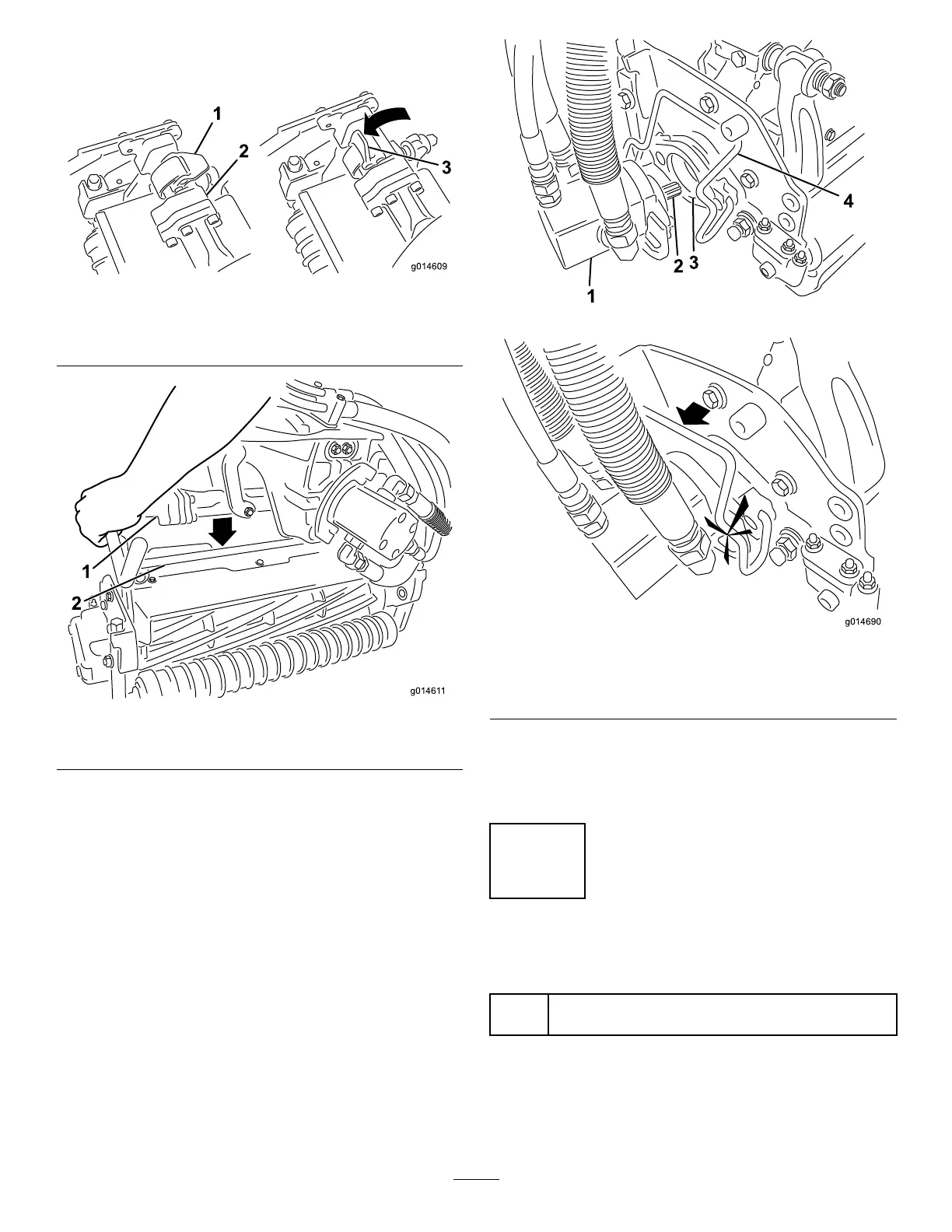
7.Coatthesplineshaftofthecuttingunitmotorwith
cleangrease(
Figure13).
8.Insertthemotorintotheleftsideofthecuttingunit
(asviewedfromtheoperator'sposition)andpullthe
motorretainingbaronthecuttingunittowardthe
motoruntilyouhearanaudible“click”fromboth
sidesofthemotor(
Figure13).
Figure13
1.Reelmotor
3.Cavity
2.Splineshaft
4.Motorretainingbar
9.Mountagrassbasketontothebaskethooksonthe
suspensionarm.
10.Repeatthisprocedurefortheothercuttingunits.
8
AddingRearWeight
Partsneededforthisprocedure:
1
Weightkit,121–6665(purchaseseparately)Note:not
requiredforunitswiththe3wheeldrivekitinstalled.
Procedure
ThisunitcomplieswiththeANSIB71.4-2004andEN
836Standardswhenequippedwithweightkit119-7129.
18

 Loading...