2.Toadjustrearrollerproceedasfollows:
•Raisetherearofthecuttingunitandplacea
blockunderthebedknife.
•Removethe(2)nutssecuringeachrollerbracket
andspacertoeachsideplatemountingange.
•Lowertherollerandscrewsfromthesideplate
mountingangesandspacers.
•Placethespacersontothescrewsontheroller
brackets.
•Re-securetherollerbracketandspacerstothe
undersideofthemountingangeswiththenuts
previouslyremoved.
3.Verifythatthebedknifetoreelcontactiscorrect.
Tipthemowertoexposethefrontandrearrollers
andthebedknife.
Note:Thepositionoftherearrollertothe
reeliscontrolledbythemachiningtolerances
oftheassembledcomponentsandparallelingis
notrequired.Alimitedamountofadjustmentis
possiblebysettingthecuttingunitonasurfaceplate
andlooseningthesideplatemountingcapscrews
(
Figure14).Adjustandre-tightencapscrews.
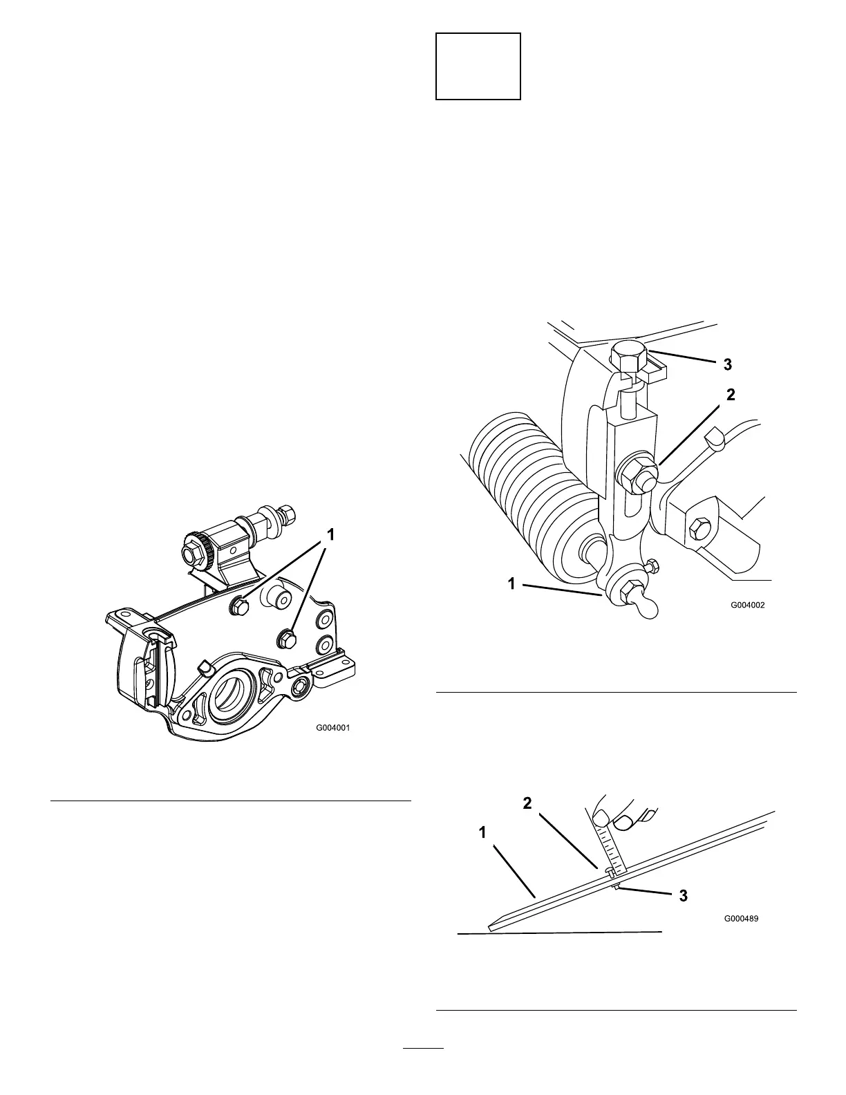
Figure14
1.Sideplatemountingcapscrews
Important:Wheneverthecuttingunithastobe
tippedtoexposethebedknife/reel,propupthe
rearofthecuttingunittomakesurethenutson
thebackendofthebedbaradjustingscrewsare
notrestingontheworksurface(Figure6).
7
AdjustingtheHeightofCut
NoPartsRequired
Procedure
Note:Forheightsofcutgreaterthan.500inch,the
highheightofcutkitmustbeinstalled.
1.Loosenthelocknutssecuringtheheight-of-cutarms
tothecuttingunitsideplates(Figure15).
Figure15
1.Height-of-cutarm
3.Adjustingscrew
2.Locknut
2.Loosenthenutonthegaugebarandsettheadjusting
screwtothedesiredheight-of-cut(Figure16).The
distancebetweenthebottomofthescrewheadand
thefaceofbaristheheight-of-cut.
Figure16
1.Gaugebar
3.Nut
2.Heightadjustingscrew
8
 Loading...


