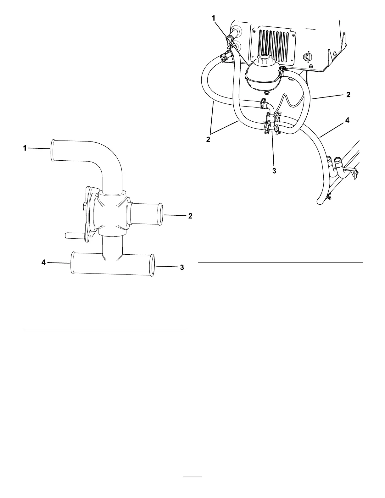
2. Connect the 2 coolant hoses that were
previously installed to the heater box to their
appropriate ports on the water valve with 2 band
clamps ( Figure 21 ).
Note: If a BOSS snowplow is installed on the
machine, route the heater core lower hose
( Figure 21 ) around the plow solenoid.
3. Connect the previously shortened thermostat
bypass hose to the water valve with a band
clamp ( Figure 21 and Figure 22 ).
4. Connect the remaining hose to the water valve
with a band clamp, then connect the other end of
the hose to the large port on the upper reservoir
with a band clamp ( Figure 21 and Figure 22 ).
g460521
Figure 21
1. T o the heater core lower
hose
3. T o the upper reservoir
large port
2. From the thermostat
bypass hose
4. T o the heater core upper
hose
g460460
Figure 22
1. Coolant tank
3. W ater valve
2. Coolant hoses (3)
4. Existing coolant hose
(previously removed
from coolant tank and
shortened)
12
 Loading...