4
Assembling the Heater Box
Assembly
Parts needed for this procedure:
1 Heater box assembly
1 Heater mount bracket
6
Carriage bolt (1/4 x 3/4 inch)
6
Locknut (1/4 inch)
1
Coolant hose (5/8 x 13 inches)
1
Coolant hose (5/8 x 26 inches)
8
V ent hose (2 x 18 inches)
2 Y -adapter
2 Band clamp
16
Cable tie
6 V ent
Procedure
Important: Do not interfere with the shifter
linkage or steering column when installing the
hoses.
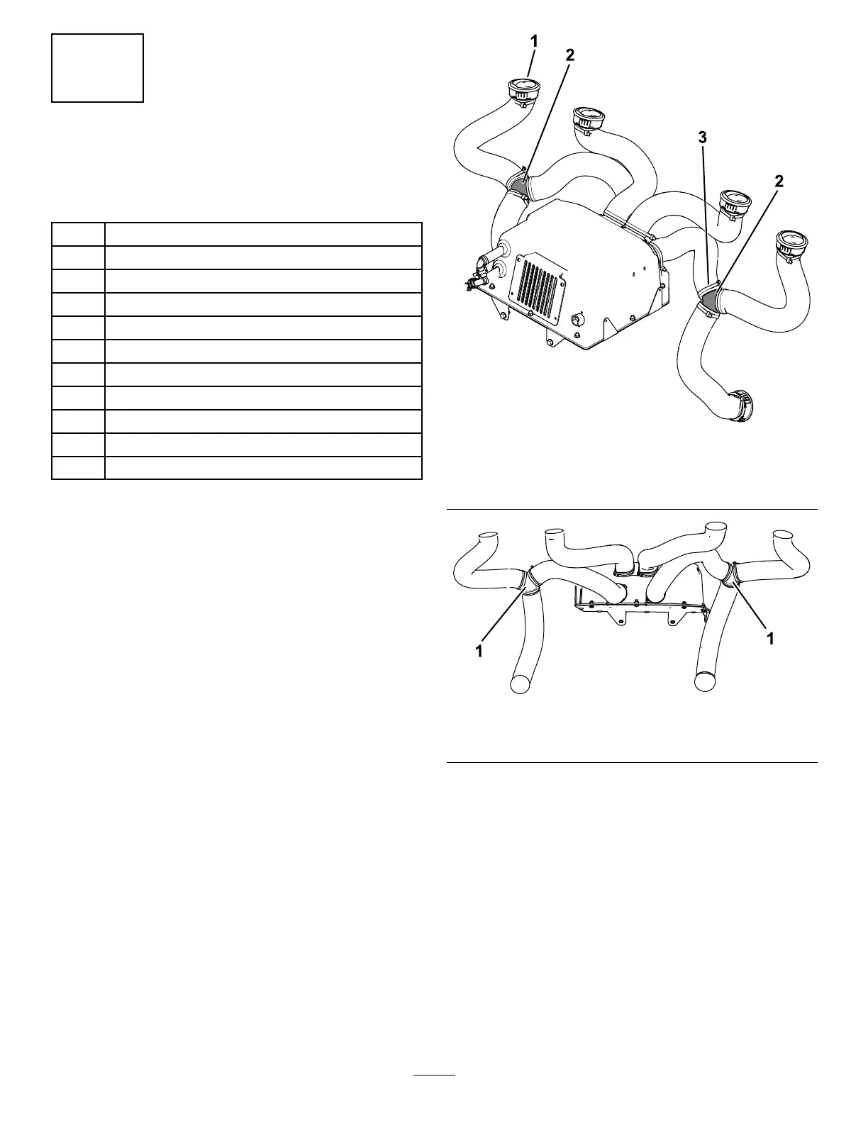
1. Connect 6 vent hoses to the adjustable vents
using 6 large cable ties ( Figure 13 ).
Note: Ensure that the vents are orientated to
blow air toward the operator on the operator ’ s
side of the machine and toward the passenger
on the passenger ’ s side.
2. Route the hoses and install the 4 adjustable
vents into the 4 top holes ( Figure 13 ).
3. Route the hoses and install the 2 adjustable
vents into the lower 2 holes ( Figure 13 ).
4. Connect the 2 outer vent hoses to the 2 lower
hoses using the 2 Y -adapters and 4 cable ties
( Figure 13 and Figure 14 ).
Connect 2 additional vent hoses to the
assembled outer vent hoses and secure them
using 2 cable ties ( Figure 13 and Figure 14 ).
5. Connect the 4 vent hoses to the heater box
using 4 cable ties ( Figure 13 and Figure 14 ).
g460891
Figure 13
1. V ent
3. Cable tie
2. Y -adapters
g460561
Figure 14
1. Outer hose assemblies
8
 Loading...