11
1538
1
2
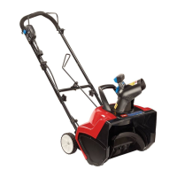
Figure
14
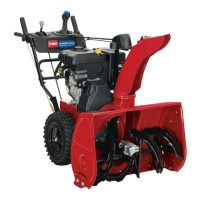
1. Rotor
shaft
2. Rotor
Note:
If you cannot remove the rotor shaft by holding the
rotor
, remove the left side cover and the skid (Fig. 15).
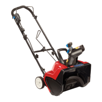
Hold the hex nut with a 7/8-in. wrench while unscrewing
the rotor shaft (Fig. 16).
3.
Hold the rotor and pull out the rotor shaft.
1539
1
2
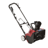
Figure
15
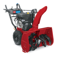
1. Left
side cover
2. Skid
1525
1
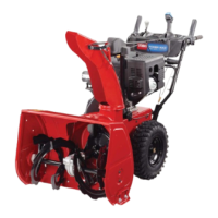
Figure
16
1. Hex
nut
4. Remove
the rotor
. Keep the washer on the right side of
the rotor for assembly
. Replace the washer if it is
worn.
5.
If necessary
, insert a new washer into the right side of
the new rotor
.
6.
Align the left side of the new rotor with the coupler
.
The three bosses on the rotor end must align with the
slots on the coupler (Fig. 17).
1518
3
4
1
2
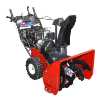
Figure
17
1. Coupler
2. Boss
3. Slot
4. Drive
hex
Note:
When mounting the coupler to the drive hex,
align the coupler tabs to the
inside.
7.
Slide the right side of the rotor into the mounting
position.
8.
Insert the rotor shaft through the rotor
. Make sure that
the shaft fits into the bearing on the right side. T
orque
it to at least 10 ft-lb.
9.
Install the cover and the skid.
Replacing
the Large Belt
1. Remove
the three screws that secure the left
side plate
to the snowthrower frame (Fig. 15). Remove the side
plate and the skid.
POTENTIAL HAZARD
•
The idler spring could fly in your face while
you r
emove it.
WHA
T CAN HAPPEN
•
Contact with the flying spring can cause
personal injury
.
HOW T
O A
V
OID THE HAZARD
• W
ear safety goggles when working with the
idler spring.
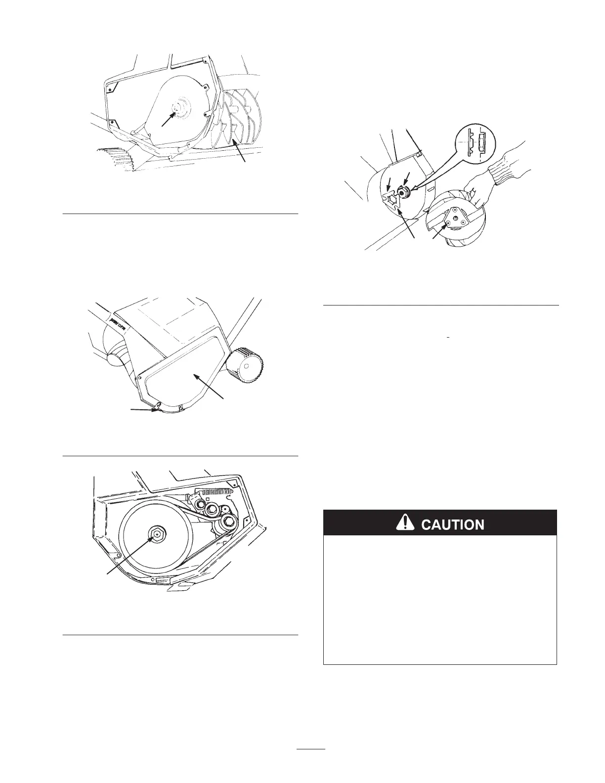
2.
Remove the idler spring from the idler arm (Fig. 18).
 Loading...