Figure 51
Mower Decks with 2 Blades
1. Blades front to rear
2. Measure from the tip of the blade to the flat surface here
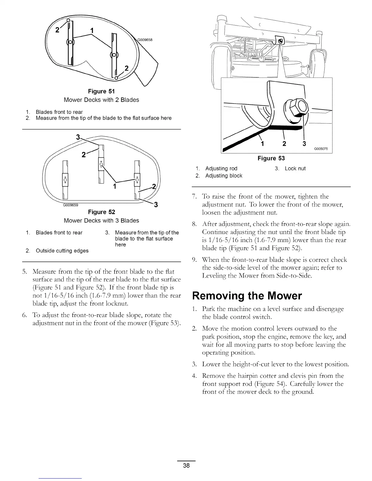
1. Adjusting rod
2. Adjusting block
1 2 3
Figure 53
3. Lock nut
G005075
,
G009659
Figure 52
Mower Decks with 3 Blades
1. Blades front to rear 3.
2. Outside cutting edges
Measure from the tip of the
blade to the flat surface
here
Measure from the tip of the front blade to the flat
surface and the tip of the rear blade to the flat surface
(Figure 51 and Figure 52). If the front blade tip is
not 1/16-5/16 inch (1.6-7.9 ram) lower than the rear
blade tip, adjust the front locMmt.
To adjust the front-to-rear blade slope, rotate the
adjustment nut in the front of the mower (Figure 53).
,
,
,
To raise the front of the mower, tighten the
adjustment nut. To lower the front of the mower,
loosen the adjustment nut.
After adjustment, check the front-to-rear slope again.
Continue adjusting the nut until the front blade tip
is 1/16-5/16 inch (1.6-7.9 ram) lower than the rear
blade tip (Figure 51 and Figure 52).
When the front-to-rear blade slope is correct check
the side-to-side level of the mower again; refer to
Leveling the Mower from Side-to-Side.
Removing the Mower
,
,
,
4.
Park the machine on a level surface and disengage
the blade control svdtch.
Move the motion control levers outward to the
park position, stop the engine, remove the ke3, and
wait for all moving parts to stop before leaving the
operating position.
Lower the height-of-cut lever to the lowest position.
Remove the hairpin cotter and clevis pin from the
front support rod (Figure 54). Carefully lower the
front of the mower deck to the ground.
38
 Loading...