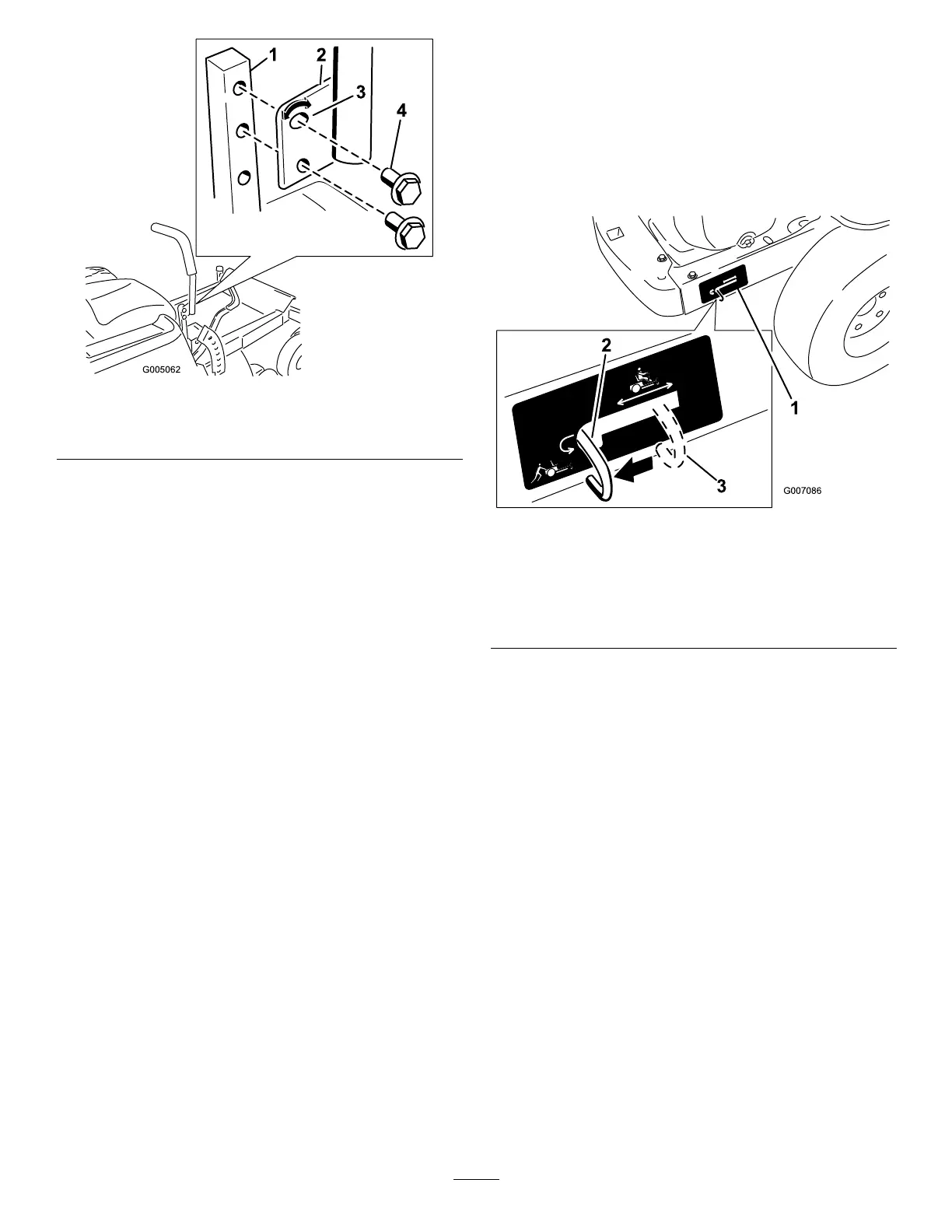
Figure20
1.Controlarmshaft3.Slotted,upperhole
2.Controllever
4.Bolt
3.Repeattheadjustmentfortheoppositecontrol
lever.
AdjustingtheTilt
Themotioncontrolleverscanbetiltedforeoraftfor
maximumoperatorcomfort.
1.Loosentheupperboltholdingthecontrolleverto
thecontrolarmshaft.
2.Loosenthelowerboltjustenoughtopivotthe
controlleverforeoraft(Figure20).Tightenboth
boltstosecurethecontrolinthenewposition.
3.Repeattheadjustmentfortheoppositecontrol
lever.
PushingtheMachinebyHand
Important:Alwayspushthemachinebyhand.
Nevertowthemachinebecausedamagemay
occur.
ToPushtheMachine
1.Parkthemachineonalevelsurfaceanddisengage
thebladecontrolswitch.
2.Movethemotioncontrolleversoutwardtopark
position,stoptheengine,removethekey,andwait
forallmovingpartstostopbeforeleavingthe
operatingposition.
3.Locatethebypassleversattherearofthemachine,
ontheleftandrightsideoftheframe.
4.Movethebypassleversrearwardandthendown
tolocktheminplaceasshowninFigure21to
disengagethewheelmotors.Repeatthisoneach
sideofthemachine.
5.Movethemotioncontrolleversinwardtothe
neutralposition.
Themachineisnowabletobepushedbyhand.
Figure21
Rightsideshown
1.Bypassleverlocation
3.Leverpositionfor
operatingthemachine
2.Leverpositionforpushing
themachine
ToOperatetheMachine
Movethebypassleversupwardandpushthemforward,
tothemiddleofthehorizontalslot(Figure21)to
engagethewheelmotors.
21
 Loading...