5.Slidetherubbercoverupthepositive(red)cable.
Disconnectthepositive(red)cablefromthebattery
post(Figure38).Retainallfasteners.
6.Removethebatteryhold-down(Figure38)andlift
thebatteryfromthebatterytray.
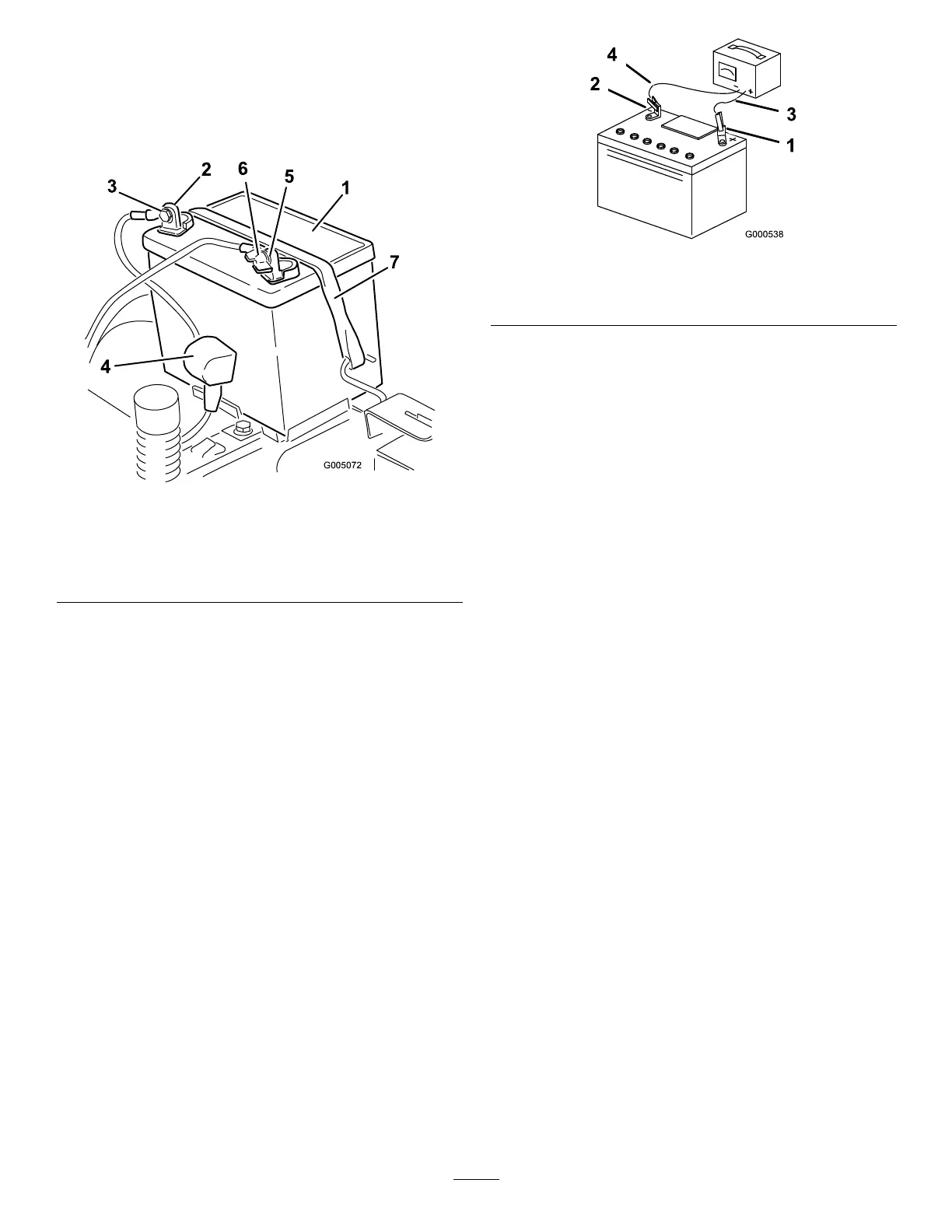
Figure38
1.Battery5.Negativebatterypost
2.Positivebatterypost6.Wingnut,washer,andbolt
3.Bolt,washer,andnut7.Batteryhold-down
4.Terminalboot
ChargingtheBattery
ServiceInterval:Beforestorage—Chargethebattery
anddisconnectbatterycables.
1.Removethebatteryfromthechassis;referto
RemovingtheBattery.
2.Chargethebatteryforaminimumof1hourat6to
10amps.Donotoverchargethebattery.
3.Whenthebatteryisfullycharged,unplugthecharger
fromtheelectricaloutlet,thendisconnectthe
chargerleadsfromthebatteryposts(Figure39).
Figure39
1.Positivebatterypost
3.Red(+)chargerlead
2.Negativebatterypost
4.Black(-)chargerlead
Note:Donotrunthemachinewiththebattery
disconnected,electricaldamagemayoccur.
InstallingtheBattery
1.Positionthebatteryinthetraywiththeterminal
poststowardtheoperatingposition(Figure38).
2.Installthepositive(red)batterycabletothepositive
(+)batteryterminalusingthefastenersremoved
previously.
3.Installthenegativebatterycabletothenegative
(-)batteryterminalusingthefastenersremoved
previously.
4.Slidetheredterminalbootontothepositive(red)
batterypost.
5.Securethebatterywiththehold-down(Figure38).
6.Installtheleftsideconsole.RefertotheAccessing
theBatteryprocedureinPremaintenanceProcedures
forinstructions.
ServicingtheFuses
Theelectricalsystemisprotectedbyfuses.Itrequires
nomaintenance;however,ifafuseblows,checkthe
component/circuitforamalfunctionorshort.
Fuse:
•MainF1-30amp,blade-type
•ChargeCircuitF2-25amp,blade-type
1.Raisetheseattogainaccesstothefuseholder
(Figure40).
2.Toreplaceafuse,pulloutonthefusetoremoveit
(Figure40).
34
 Loading...