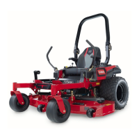
3.Measurefromthetipofthebladetothelevel
surface.
g014973
Figure55
1.Blade,inpositionformeasuring
2.Levelsurface
3.Measureddistancebetweenbladeandsurface(A)
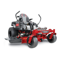
4.Rotatethesameblade180degreessothat
theopposingcuttingedgeisnowinthesame
position.
g014974
Figure56
1.Blade,sidepreviouslymeasured
2.Measurementpositionusedpreviously
3.Opposingsideofbladebeingmovedintomeasurement
position
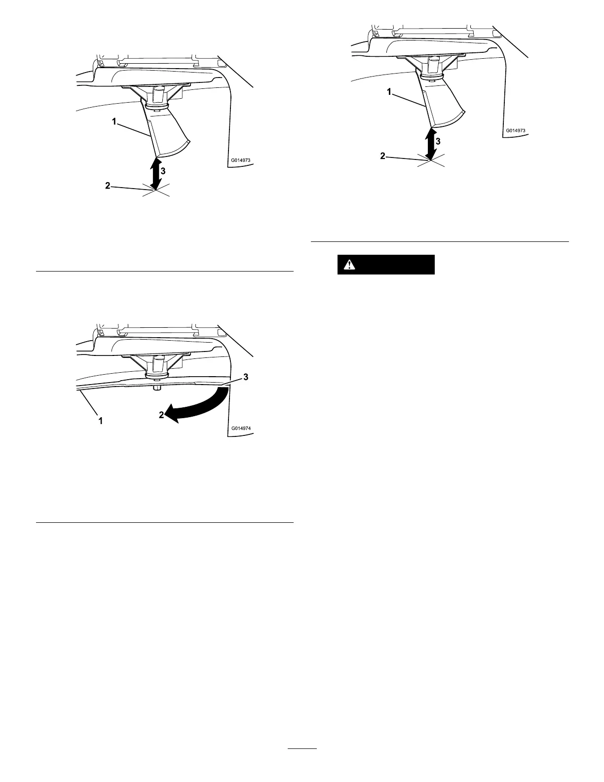
5.Measurefromthetipofthebladetotheat
surfacehere.
Note:Themeasuredvarianceshouldbeno
morethan3mm(1/8inch).
g014973
Figure57
1.Opposingbladeedge,inpositionformeasuring
2.Levelsurface
3.Secondmeasureddistancebetweenbladeandsurface(B)
WARNING
Abladethatisbentordamagedcould
breakapartandcouldseriouslyinjureor
killyouorbystanders.
•Alwaysreplaceabentordamaged
bladewithanewblade.
•Neverleorcreatesharpnotchesin
theedgesorsurfacesoftheblade.
A.IfthedifferencebetweenAandBisgreater
than3mm(1/8inch)replacethebladewith
anewblade;refertoRemovingtheBlades
(page45)andInstallingtheBlades(page
46).
Note:Ifabentbladeisreplacedwithanew
oneandthedimensionobtainedcontinues
toexceed3mm(1/8inch),thebladespindle
couldbebent.ContactanAuthorizedToro
Dealerforservice.
B.Ifthevarianceiswithinconstraints,move
tostep6.
6.Performsteps2,3,4,and5ontheotherblade.
RemovingtheBlades
Replaceabladewheneveritstrikesanobject,
isoutofbalance,orisbent.T oensureoptimum
performanceandcontinuedsafetyconformanceofthe
machine,useonlygenuineT ororeplacementblades.
Replacementbladesmadebyothermanufacturers
mayresultinnon-conformancewithsafetystandards.
Holdthebladeendusingaragorthickly-padded
glove.Removethebladebolt,curvedwasher,and
bladefromthespindleshaft(Figure58).
45
 Loading...