ChangingtheBladesforSide
DischargeMowerDecks
RemovingtheBladesforSideDischarge
MowerDecks
Replaceabladeifithitsanobject,ifthebladeisout
ofbalance,orifthebladeisbent.Toensureoptimum
performanceandcontinuedsafetyconformanceof
themachine,usegenuineTororeplacementblades.
Replacementbladesmadebyothermanufacturers
mayresultinnonconformancewithsafetystandards.
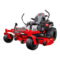
1.Holdthespindleshaftwithawrench.
2.Removethebladebolt,curvedwasher,and
bladefromthespindleshaft(Figure108).
g017443
Figure108
1.Sailareaoftheblade
4.Bladebolt
2.Blade
5.Spindleshaft
3.Curvedwasher
InstallingtheBladesforSideDischarge
MowerDecks
1.Installthebladeontothespindleshaft(Figure
108).
Important:Thecurvedpartoftheblade
mustpointupwardtowardtheinsideofthe
mowertoensurepropercutting.
2.Installthecurvedwasherandbladebolt(Figure
108).
Note:Installthecurved-washerconetoward
thebolthead.
3.Torquethebladeboltto115to150N∙m(85to
110ft-lb).
ChangingtheBladesforRear
DischargeMowerDecks
RemovingtheBladesforRearDischarge
MowerDecks
Replaceabladeifithitsanobject,isoutofbalance,
orifitisbent.T oensureoptimumperformanceand
continuedsafetyconformanceofthemachine,use
genuineTororeplacementblades.Replacement
bladesmadebyothermanufacturersmayresultin
nonconformancewithsafetystandards.
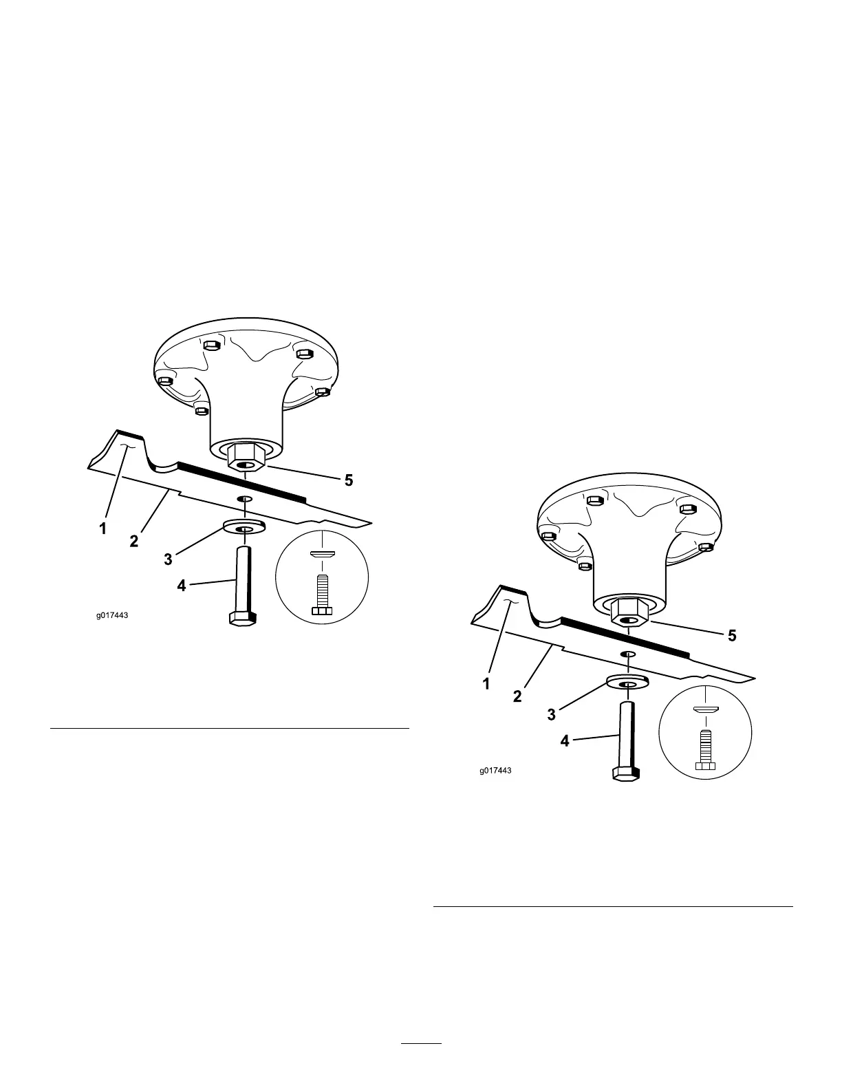
1.Holdthebladeendusingaragorathickly
paddedglove.
2.Removetheleftandcenterbladebolt,curved
washer,andbladefromthespindleshaft(Figure
109).
3.Removetherightbladebolt(left-handthreaded
bolt),curvedwasher,andbladefromthespindle
shaft(Figure110).
Note:Notethetypebladeandwhereeach
bladeisinstalled.SeeFigure110forthecorrect
position.
g017443
Figure109
LeftandCenterSpindleShown
1.Sailareaoftheblade
4.Bladebolt
2.Blade
5.Spindleshaft
3.Curvedwasher
InstallingtheBladesforRearDischarge
MowerDecks
Important:Therightbladeonthismower
deckiscounter-rotatingandusesaleft-hand
76

 Loading...