12
Operation
Think
Safety First
Please carefully read all the safety instructions and
symbols in the safety section. Knowing this
information could help you, your family, pets or
bystanders avoid injury.
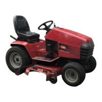
Controls
Become familiar with all the controls (Fig. 1) before
you start the engine and operate the machine.
2
3
4
8
9
10
12
1200
1
6
11
5
14
7
13
Figure 1
1. Steering
wheel
2.
Ignition switch
3.
Brake pedal
4.
Parking brake lever
5.
Ground speed selector
6.
Throttle lever
7.
Choke lever
8.
Power take of
f (PT
O)
9.
Cruise control switch
10.
Indicator control
module/Hourmeter
11.
Attachment lift lever
12. T
ilt wheel lever
13.
Hood opening
14.
Dial-a-height knob
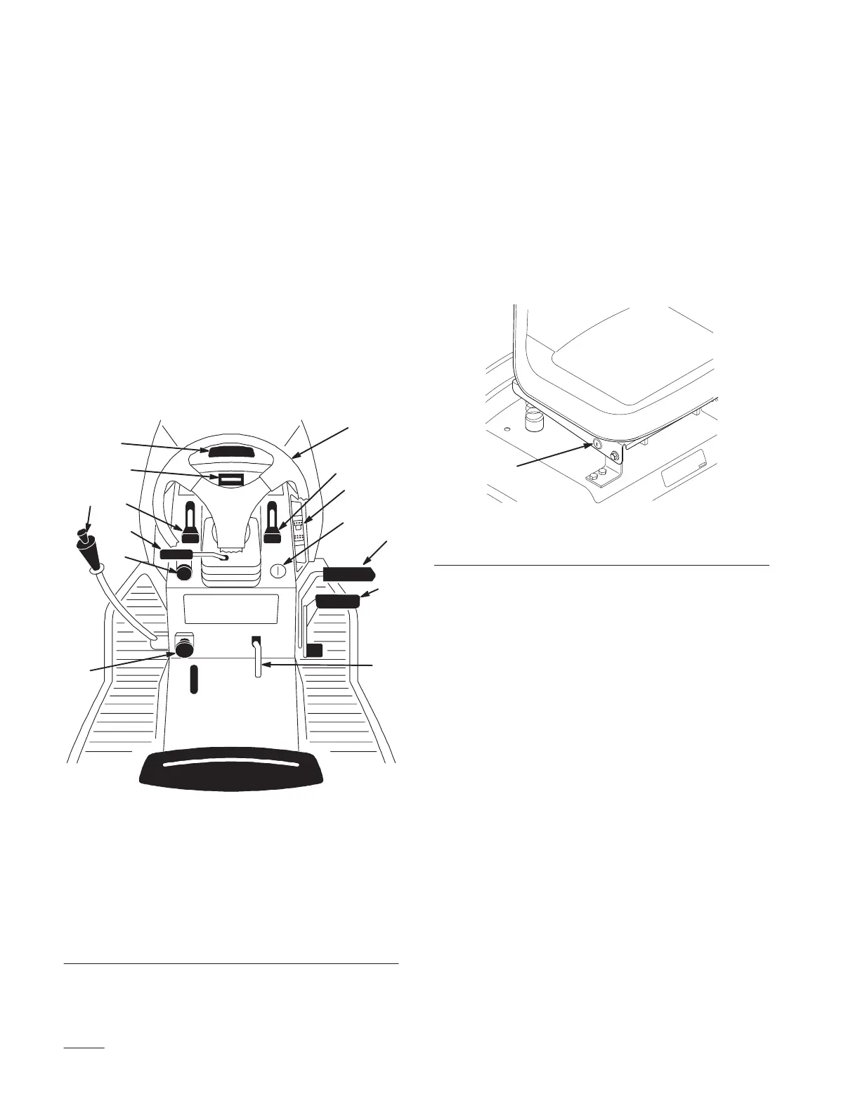
Key
Choice Switch
A turn and release switch used for deactivating the
“Operating–In–Reverse” interlock feature. Located
on the seat bracket on the right side just below the
seat (Fig. 2).
m–4220
1
Figure 2
1. “Key
Choice” switch
Parking Brake
Always set the parking brake when you stop the
machine or leave it unattended.
Setting the Parking Brake
1. Push the brake pedal (Fig. 3) down and hold it in
the depressed position.
2. Lift the parking brake lever (Fig. 3) up and
gradually take your foot off the brake pedal. The
brake pedal should stay in the depressed (locked)
position.
Releasing the Parking Brake
1. Push down on the brake pedal (Fig. 3). The
parking brake lever should release.
2. Gradually release the brake pedal.
 Loading...